
Short-distance plane cam type lifting device of printing working table

A flat cam and lifting device technology, applied in rotary printing presses, printing, printing presses, etc., can solve the problem that operators and designers have high professional knowledge requirements, design machine fine-tuning devices take up a lot of space, and cannot achieve accurate lifting in short distances. Positioning and other issues to achieve the effect of saving operation space, shortening development time, and convenient design

Inactive Publication Date: 2013-09-11
昆山富山精密设备有限公司
View PDF7 Cites 3 Cited by
  • Summary
  • Abstract
  • Description
  • Claims
  • Application Information

AI Technical Summary

Problems solved by technology

[0002] At present, the workbench (mobile workbench) used in the printing equipment industry is multi-axial movement, which is expensive, complicated in design, and requires high professional knowledge of operators and designers.
Among the existing lifting devices for printing tables, the common ones are high manufacturing costs and complex design structures. For example, the fine-tuning device for the design machine takes up a lot of space, and the manufacturing of the table moving mechanism uses servo motors to drive ball screws, linear guide rails or Driven by rack and pinion, but the effect cannot achieve short-distance lifting and precise positioning, and it will result in high costs and the need to write complex control programs

Method used


Image

  • Short-distance plane cam type lifting device of printing working table

Examples


Embodiment

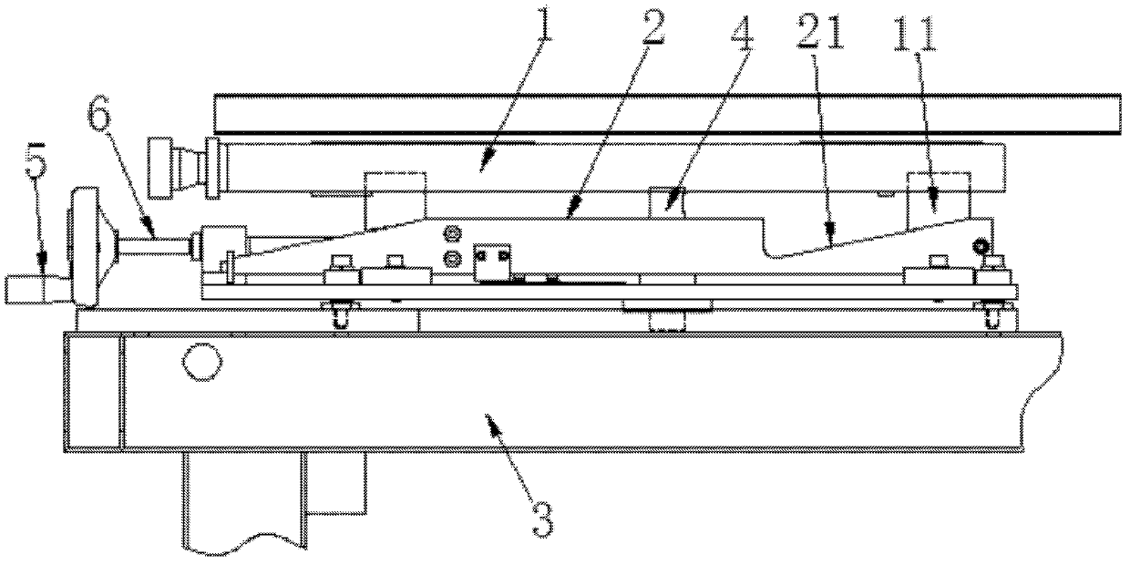
[0011] Embodiment: a short-distance planar cam-type printing table lifting device, including a work table 1, a traction table 2 and a frame table 3, and a lifting mechanism 4, which is composed of a guide post and a guide sleeve. The guide post can be vertically lifted relative to the guide sleeve, the lower end of the guide sleeve is fixed on the upper surface of the rack table 3, and the upper end of the guide post is fixed on the lower surface of the work table 1, and the traction table is connected with A transmission mechanism, the transmission mechanism is connected with a drive mechanism, the drive mechanism can drive the transmission mechanism to drive the traction table to move linearly on the rack table, and the upper surface of the traction table 2 is provided with a slope guide Groove 21, the slope direction of the slope guide groove is consistent with the moving direction of the traction table, the slope guide block 11 corresponding to the slope guide groove is fix...


PUM


Abstract

The invention discloses a short-distance plane cam type lifting device of a printing working table. The short-distance plane cam type lifting device mainly comprises a working table board, a traction table board, a rack table board and a lifting mechanism, wherein a ramp guide block is fixed on the working table board; a ramp guide slot is formed in the traction table board, and the traction table board can linearly reciprocate; and the lifting mechanism is connected with the rack table board and the working table board. When a driving mechanism drives a transmission mechanism to drive the traction table board to move on the rack table board, the ramp guide slot and the ramp guide block are interacted, and a guide post of the lifting mechanism can perpendicularly ascend and descend relative to a guide sleeve, so that the working table board can move upward and downward. The lifting device is applicable to high-accuracy fine adjustment of the upward and downward movement of the working table, and adopts a plane cam structure, so that the lifting device is simple and compact in structure and convenient to design; the operating space occupied by a conventional fine adjustment device is not required; and when a crank handle is used for driving and pulling a screw rod to perform transmission, the cost can be reduced, the operation is easy, and the failure rate is low.

Description

technical field [0001] The invention belongs to the field of printing equipment, and in particular relates to a worktable lift mechanism of printing equipment. Background technique [0002] At present, the workbench (mobile workbench) used in the printing equipment industry is multi-axially movable, which is expensive, complicated in design, and requires high professional knowledge of operators and designers. Among the existing lifting devices for printing tables, the common ones are high manufacturing costs and complex design structures. For example, the fine-tuning device for the design machine takes up a lot of space, and the manufacturing of the table moving mechanism uses servo motors to drive ball screws, linear guide rails or Driven by rack and pinion, but the effect cannot achieve short-distance lifting and precise positioning, and it will result in high costs and the need to write complex control programs. Contents of the invention [0003] In order to overcome t...

Claims


Application Information

Patent Timeline
IPC IPC(8): B41F17/00
Inventor 阳太平张健周小丽
Owner 昆山富山精密设备有限公司
Learn More