
Construction method of anti-seepage structure in inclined shaft section of diversion tunnel

A technology for water diversion tunnels and construction methods, applied in water conservancy projects, marine engineering, hydropower generation and other directions, can solve problems affecting power generation benefits, and achieve the effect of ensuring power generation benefits

Active Publication Date: 2015-09-30
POWERCHINA HUADONG ENG COPORATION LTD
View PDF3 Cites 0 Cited by
  • Summary
  • Abstract
  • Description
  • Claims
  • Application Information

AI Technical Summary

Problems solved by technology

However, venting the tunnel for treatment will seriously affect the power generation efficiency

Method used


Image

  • Construction method of anti-seepage structure in inclined shaft section of diversion tunnel
  • Construction method of anti-seepage structure in inclined shaft section of diversion tunnel
  • Construction method of anti-seepage structure in inclined shaft section of diversion tunnel

Examples


Embodiment 1

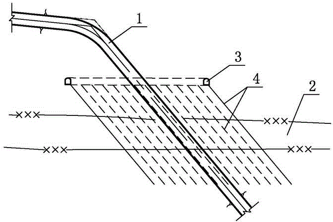
[0024] Embodiment 1: as figure 1 As shown, the construction steps of this embodiment are as follows,

[0025] a. According to the geological survey data and leakage detection analysis, determine the leakage location of the inclined shaft 1 and the water leakage area 2 of the surrounding rock.

[0026] b. In the non-leakage area of ​​the surrounding rock above the leaking part, and on the periphery of the inclined shaft 1, excavate a circle of horizontally arranged annular grouting corridors 3 using the construction branch hole 7; after the excavation of the grouting corridor 3 is completed, first carry out Reinforced concrete lining construction, followed by backfill grouting and consolidation grouting for the lining. After the reinforced concrete lining construction is completed, the top arch will be hollowed out, and backfill grouting is required; the consolidation grouting is carried out 7 days after the backfill grouting is completed, the purpose is to strengthen the rock...

Embodiment 2

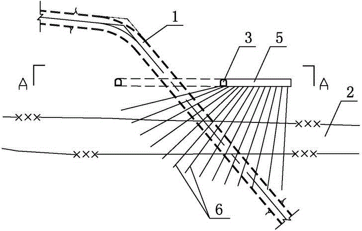
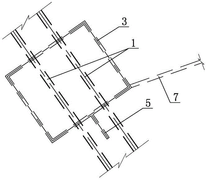
[0029] Embodiment 2: as figure 2 , image 3 As shown, this embodiment is mainly aimed at the situation of two or more than two tunnels, and the specific construction steps are as follows,

[0030] a. According to the geological survey data and leakage detection analysis, determine the leakage location of the inclined shaft 1 and the water leakage area 2 of the surrounding rock.

[0031] b. In the non-leakage area of ​​the surrounding rock above the leakage site, excavate a circle of horizontally arranged annular grouting corridors 3 by using the construction branch hole 7 around the inclined shaft 1, and excavate a circular grouting corridor 3 between two adjacent inclined shafts 1 The grouting branch hole 5 connected with the grouting gallery 3, in this example, the grouting branch hole 5 and the grouting gallery 3 are located on the same level.

[0032] c. Carry out reinforced concrete lining construction for the grouting corridor 3 and grouting branch hole 5, and then ca...


PUM


Abstract

The invention relates to a construction method of a leakage-proof structure of an inclined / vertical well section of a diversion tunnel and aims at providing the construction method of the leakage-proof structure of the inclined / vertical well section of the diversion tunnel to ensure benefits of power generation. The technical scheme of the construction method of the leakage-proof structure of the inclined / vertical well section of the diversion tunnel comprises: a, determining a leakage portion of an inclined / vertical well and a water leakage area of surrounding rocks according to geological survey data and leakage detection analyses; b, excavating a circle of ring-shaped grouting gallery in a non-water-leakage area of the surrounding rocks above the leakage portion and on the periphery of the inclined / vertical well, performing reinforced concrete lining construction, and then subjecting a lining to backfill grouting and consolidation grouting; c, drilling one or two circles of evenly-distributed curtain grouting holes I on a grouting gallery base plate, wherein every curtain grouting hole I is arranged in the axial direction of the inclined / vertical well, and the bottom of every curtain grouting hole I penetrates the water leakage area of the surrounding rocks and extends inside a non-water-leakage area of the surrounding rocks, which is under the leakage portion; and d, performing curtain grouting through every curtain grouting hole I to form a ring-shaped underground retention wall on the periphery of the inclined / vertical well.

Description

technical field [0001] The invention relates to a construction method for an anti-seepage structure of an inclined well section of a water diversion tunnel, which is mainly applicable to water conservancy and hydropower projects. Background technique [0002] In recent years, my country's water conservancy and hydropower industry has developed rapidly, and a large number of large and medium-sized hydropower stations with medium and high heads have been completed and put into operation. Under the premise of satisfying the Norwegian criteria and the minimum ground stress, hydraulic tunnels are generally lined with reinforced concrete, and few engineering diversion tunnels use an all-steel-lined structure. Under the action of medium and high water heads, the reinforced concrete lining is used as a permeable lining, and the internal water pressure directly acts on the surrounding rock. When the surrounding rock has a certain permeability coefficient, a certain degree of water le...

Claims


Application Information

Patent Timeline
Patent Type & Authority Patents(China)
IPC IPC(8): E02B9/06E02B3/16
CPCY02E10/22Y02E10/20
Inventor 赵瑞存张伟沈明罗前进
Owner POWERCHINA HUADONG ENG COPORATION LTD
Learn More