
Real-time monitoring system and method for fire water supply system of building

A water supply system and real-time monitoring technology, applied in fire rescue and other fields, can solve the problems that fire managers cannot understand the water supply at the end of the pipeline in real time, heavy workload, flooding, etc., to improve fire prevention and control capabilities and improve work efficiency , Guarantee complete and effective effect

Active Publication Date: 2013-09-04
SHENYANG FIRE RES INST OF MEM
View PDF4 Cites 11 Cited by
  • Summary
  • Abstract
  • Description
  • Claims
  • Application Information

AI Technical Summary

Problems solved by technology

[0004] (1) There is generally no pressure detection device at the end of the pipeline in the water supply network, so it is impossible to monitor the actual water pressure in the pipeline in real time;
[0005] (2) The end test points of the water supply pipe network are generally set in concealed locations such as roofs, without automatic water discharge control devices
The daily periodic water discharge test stipulated in the fire protection facility maintenance regulations is generally carried out manually, and the operation of the terminal water discharge test is cumbersome, and there is also a risk of flooding or water leakage;
[0006] (3) Without a unified automatic monitoring and management platform, it is impossible to realize the centralized water pressure monitoring and water discharge test of the fire water supply system
Due to the relatively complex fire water supply system of high-rise buildings, full-time personnel are required to conduct manual inspection and testing at the end of each pipeline on each floor. The workload is heavy and the situation of the fire water supply system cannot be accurately judged, and the fire management manager cannot understand the end of the pipeline in real time. water supply situation

Method used


Image

  • Real-time monitoring system and method for fire water supply system of building

Examples


Embodiment Construction

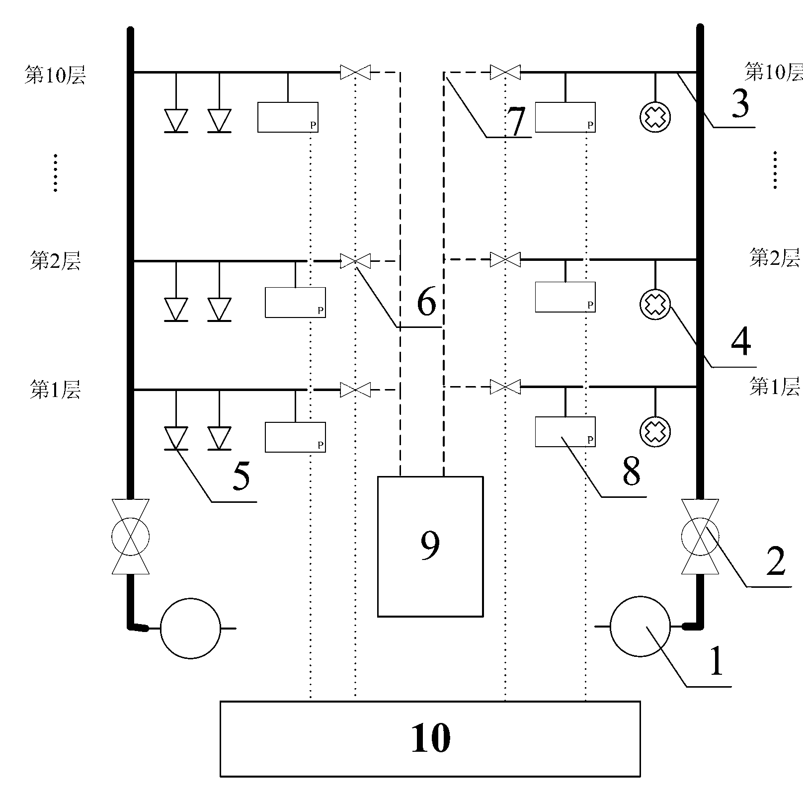
[0016] A real-time monitoring system for building fire water supply system, such as figure 1 As shown, including the fire water supply system and the monitoring host 10, the fire water supply system includes fire water source, voltage stabilizing equipment, fire pump 1, maintenance valve 2, water supply pipeline 3, fire hydrant 4, sprinkler head 5; the water supply in the fire water supply system A water discharge solenoid valve 6 is installed at the end of the pipeline 3 for water discharge control at the end. The other end of the water discharge solenoid valve 6 is connected to the water discharge pipeline 7. A water pressure sensor 8 is installed at the front end of the solenoid valve 6 to measure the water inside the pipeline. The pressure value, the discharge pipeline 7 is connected with the low-level fire water tank 9 or the sewer pipe network, and the water pressure sensor 8 and the discharge solenoid valve 6 are connected with the monitoring host 10 through the 485 bus....


PUM


Abstract

The invention relates to a real-time monitoring system and method for a fire water supply system of a building. The system comprises a fire water supply system and a monitoring host, wherein a drainage electromagnetic valve is mounted at the tail end of a water supply pipeline of the fire water supply system and used for controlling drainage of the tail end of the water supply pipeline, and the other end of the drainage electromagnetic valve is connected with a drainage pipeline; a water pressure sensor is mounted at the front end of the electromagnetic valve and used for measuring water pressure inside the pipeline; the drainage pipeline is connected with a low-position fire water tank or a drain pipe net; and the water pressure sensor and the drainage electromagnetic valve are connected with the monitoring host through communication pipelines. The system can timely find hidden dangers caused due to blocking of the pipeline or mistakenly closing of a pipe valve during operation of the fire water supply system; and the system can monitor pressure of water supply pipelines in real time, and can remotely control testing of drainage of the pipelines, so that daily maintenance and test operating procedures of the fire water supply system are simplified substantially, and the working efficiency of fire control safety management is improved.

Description

technical field [0001] The invention relates to a real-time monitoring system and method for a building fire-fighting water supply system, in particular to a real-time monitoring system and method for a building fire-fighting water supply system based on automatic water release control by using a circulation pipeline and a drain pipeline. Background technique [0002] As an important part of the building fire protection system, the fire water supply system has been widely installed and used in a large number of buildings. A large number of fire cases have shown that a sound and effective fire water supply system can control and extinguish the fire in a timely manner at the initial stage of the fire. It plays an important role in reducing fire losses and realizing building fire self-prevention and self-rescue. [0003] The fire water supply system generally includes fire water sources, fire booster (stabilizer) equipment, fire pumps, valves, water supply pipe networks and man...

Claims


Application Information

Patent Timeline
IPC IPC(8): A62C37/50
Inventor 王军刘濛隋虎林马青波杨树峰
Owner SHENYANG FIRE RES INST OF MEM
Learn More