
Bee pollen trap

A dedusting and dedusting technology, which is applied in beehives, beekeeping, applications, etc., can solve the problems of bees flying around in a circle, and achieve the effects of solving the low pollen collection rate, improving the utilization rate, and avoiding inefficiency

Active Publication Date: 2013-09-04
吴晓彬
View PDF8 Cites 9 Cited by
  • Summary
  • Abstract
  • Description
  • Claims
  • Application Information

AI Technical Summary

Problems solved by technology

[0005] The object of the present invention is to provide a bee de-powdering device, which solves the problem that some bees fly in circles near the one-way channel during the use of the current de-powdering device and causes confusion, further improves the de-powdering efficiency, and avoids pollen collection during pollen collection. The peak period will cause greater losses

Method used


Image

  • Bee pollen trap
  • Bee pollen trap
  • Bee pollen trap

Examples


Embodiment 1

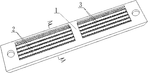
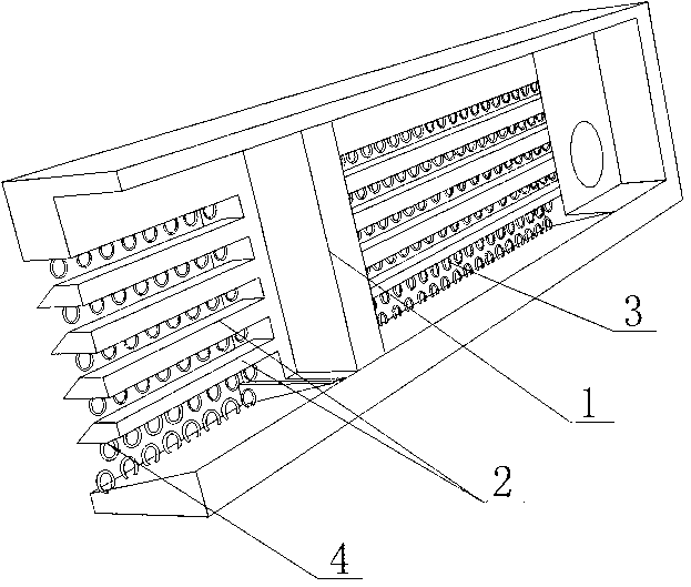
[0029] like Figures 1 to 4 Shown, a kind of honeybee powder remover of the present invention, comprises powder remover board body 1, is provided with four spacers 2 on the board body of remover powder device 1, under the upper border of powder remover board body 1 and four A row of depowder holes 3 are arranged below the spacer 2, and the cross-section of the lower frame of the depowder plate body 1 is set as a right-angled trapezoid. The bottom frame slope of β has a row of powder removal holes 3 installed on the slope. The diameter of the powder removal holes 3 on this row of slopes is 1mm larger than the diameter of the five rows of powder removal holes 3 above it. In the actual production process, due to Due to the difference in process, the diameter difference can be controlled within 0.8-1.2mm, which does not affect the use; the fourth spacer 2 from top to bottom is provided with a spacer slope 4, and the cross section of the spacer 2 is a right-angled trapezoid , the ...

Embodiment 2

[0031] like Figure 5 As shown, the difference between this embodiment and the first embodiment is that the spacer 2 forms a parallelogram in cross section after cutting off the inclined surface of the spacer. At this time, the height of the cut right triangle is the same as the height of the spacer 2 .


PUM


Abstract

The invention discloses a bee pollen trap. The bee pollen trap comprises a pollen trap plate body. A plurality of spacing bars are arranged in the pollen trap plate body. Pollen trapping holes are formed between the pollen trap plate body and the spacing bars, and pollen trapping holes are also formed between every two adjacent spacing bars. Unidirectional passages are formed in the pollen trap plate body and located in a zone without the spacing bars on the pollen trap plate body. According to the bee pollen trap, the unidirectional passages are adjusted to the zone without the spacing bars, and therefore bees have only one choice that the bees enter a beehive from the pollen trapping holes while the unidirectional passages are only used for exiting. Compared with the prior art, the bee pollen trap has significant substantive advantages due to the fact that nobody has studied the problem, any literary inscription does not exist in the field and the applicant obtains the technical scheme of the bee pollen trap through long-term observation, analysis and experimentation. The bee pollen trap solves the problem that part of the bees pass round the unidirectional passages and the problem that efficiency is low because the bees do not enter the beehive in a peak season for trapping pollen. In addition, the bee pollen trap improves the use ratio of the pollen and has significant advanced nature.

Description

technical field [0001] The invention relates to a powder remover for a bee breeding box, in particular to a bee powder remover. Background technique [0002] Pollen is a high-value natural nutrient, which has been widely used in catering, cosmetics and other industries. At present, collecting pollen is when honeybee enters hive box, is provided with the entrance hole of suitable size, makes honeybee be de-pollinated when passing through entrance hole, promptly the pollen collected on body is squeezed when honeybee enters into nest hole. [0003] In the prior art, Wu Guochuan applied for an invention patent titled "An Improved Structure of a Bee Deflourer" on April 26, 2012. The patent number is: ZL 201220182785.5. This patent is currently the most advanced technical solution , this invention patent solves the above problems very well. In the actual production and use process, it also solves two problems. First: the shape of the pollen-carrying part of the bee is irregular. ...

Claims


Application Information

Patent Timeline
Patent Type & Authority Applications(China)
IPC IPC(8): A01K47/06
Inventor 吴晓彬
Owner 吴晓彬
Learn More