
Fuse with sleeve structure and mounting method

A fuse and bushing technology, applied in the direction of electrical component structure associations, emergency protection devices, electrical components, etc., can solve the problems of transformer oil leakage and easy live operation, so as to reduce the risk of insulating oil leakage and improve the safety of use. Sex, volume reduction effect

Active Publication Date: 2013-08-28
深圳市罗庚电气有限公司
View PDF5 Cites 6 Cited by
  • Summary
  • Abstract
  • Description
  • Claims
  • Application Information

AI Technical Summary

Problems solved by technology

[0003] The first purpose of the present invention is to overcome the disadvantages of transformer bushings and fuse installation methods in the prior art that are likely to cause serious accidents such as transformer oil leakage and easy electrified operation, and provide a fuse with a bushing structure
[0004] The second purpose of the present invention is to overcome the disadvantages of transformer bushings and fuse installation methods in the prior art that are likely to cause serious accidents such as transformer oil leakage and easy live operation, and provide a method for installing the above-mentioned fuse

Method used


Image

  • Fuse with sleeve structure and mounting method
  • Fuse with sleeve structure and mounting method
  • Fuse with sleeve structure and mounting method

Examples


Embodiment Construction

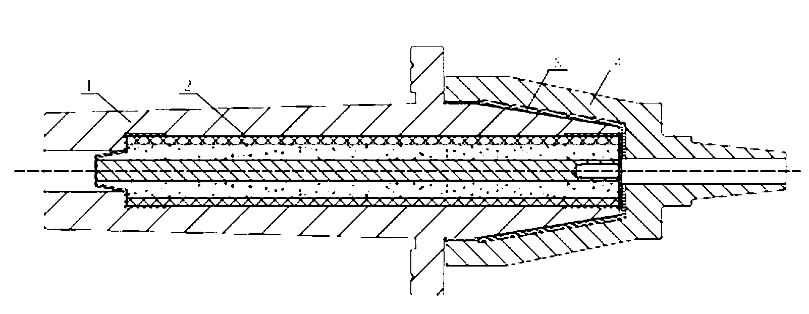
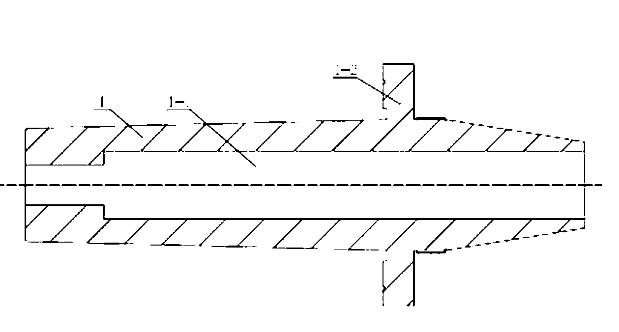
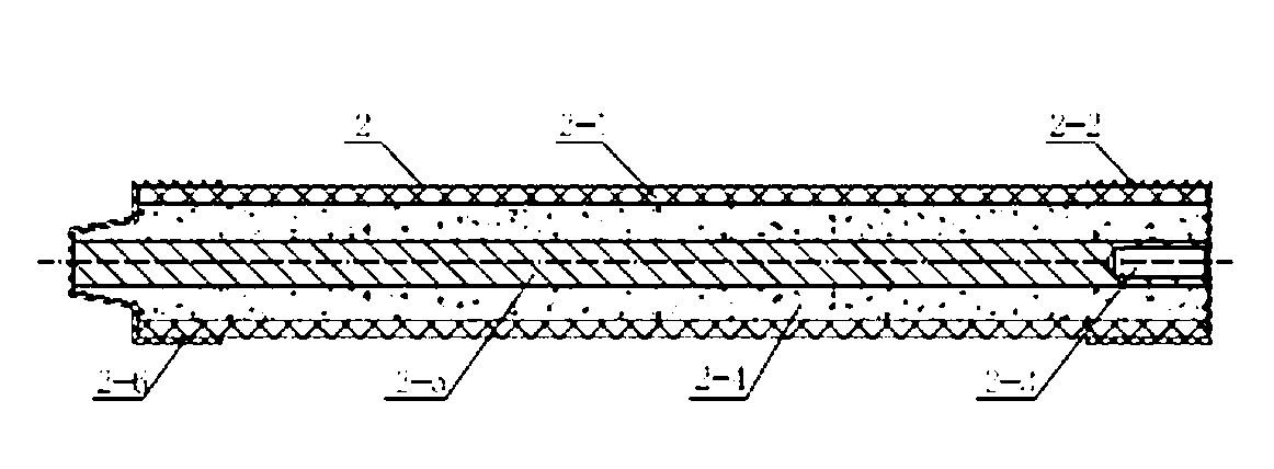
[0023] as attached Figures 1 to 7 As shown, a fuse with sleeve structure in this embodiment, the fuse 2 includes a fuse outer layer 2-1, quartz sand 2-4, a fuse conductor 2-5, and winding connection ends at both ends of the fuse Metal guide block 2-6 and cable connection end metal guide block 2-2. Quartz sand 2-4 is arranged between the fuse conductor 2-5 and the outer layer of the fuse 2-1, and the metal guide block 2-6 at the winding connection end and the metal guide block 2-2 at the cable connection end are respectively fixed on the outer layer of the fuse 2-1, the fuse 2 forms a closed structure. It also includes a sleeve, and the sleeve includes an inner sleeve 1 , an outer sleeve 4 and an inner protection sleeve 3 of the sleeve. The inner sleeve 1 is provided with a fuse insertion hole 1-1, the size of the inner wall of the fuse insertion hole 1-1 corresponds to the size of the outer wall of the fuse 2, and the two can be interference fit after the fuse 2 is inserted...


PUM


Abstract

The invention provides a fuse with a sleeve structure and a mounting method, aims to overcome the defects that a transformer leaks oil and is easily subjected to hot-line work, caused by installation manners of a sleeve and a fuse of a transformer in the prior art, and provides the fuse with the sleeve structure. The sleeve comprises an inner sleeve, an outer sleeve and a sleeve inner protection cover, wherein the inner sleeve is internally provided with a fuse inserting hole; the fuse is inserted into the fuse inserting hole; the sleeve inner protection cover covers outside the inner sleeve and tightly presses the fuse; the outer sleeve covers the inner sleeve and the sleeve inner protection cover; and the outer sleeve is fixedly connected with the inner sleeve. The invention further provides a mounting method of the fuse. The mounting method comprises the following steps: A, inserting the fuse into the inner sleeve; B, fastening the fuse into the inner sleeve; C, fixedly mounting the fuse with the sleeve structure on a box body of the transformer; D, electrically connecting a power cable and the fuse; and E, electrically connecting a high-voltage side winding with the fuse. According to the fuse with the sleeve structure and the mounting method disclosed by the invention, the volume of the transformer is reduced and the risk of leaking oil is reduced; and the fuse is applicable to the circumstance using the transformer.

Description

technical field [0001] The invention relates to an internal component of a transformer, in particular to a fuse with a bushing structure used in a transformer of 35kV or below and an installation method thereof. Background technique [0002] At present, the bushing and fuse used in transformers of 35kV and below are two sets of devices installed in the oil-immersed transformer box respectively. One end of the wire in the bushing is electrically connected to the cable outside the transformer box, and the other end is insulated in the transformer box. Under the protection of the oil, it is connected in series with the fuse, and the other end of the fuse is connected to the high-voltage side winding of the transformer. Usually, transformers of 35kV and below use three sets of bushings and fuses. It is necessary to open six holes in the transformer box for installing bushings and fuses, which not only increases the volume of the transformer, but also increases the oil leakage of...

Claims


Application Information

Patent Timeline
Patent Type & Authority Applications(China)
IPC IPC(8): H01H85/02H01F27/40
Inventor 陈鸿滨何省运
Owner 深圳市罗庚电气有限公司
Learn More