Multilane free-flow electronic toll collection system and method based on multi-beam antenna
An electronic toll collection system and multi-beam antenna technology, which is applied in the field of multi-lane free flow electronic toll collection system, can solve the problem that the positioning information cannot be well adapted to the horizontal vehicle position information, the inspection of violations cannot be realized, and it is difficult to realize the multi-lane free flow electronic toll collection system. Fees and other issues
- Summary
- Abstract
- Description
- Claims
- Application Information
AI Technical Summary
Problems solved by technology
Method used
Image
Examples
Embodiment 1
[0085] Example 1: Multi-lane free-flow front-end lane layout based on two-dimensional position matching
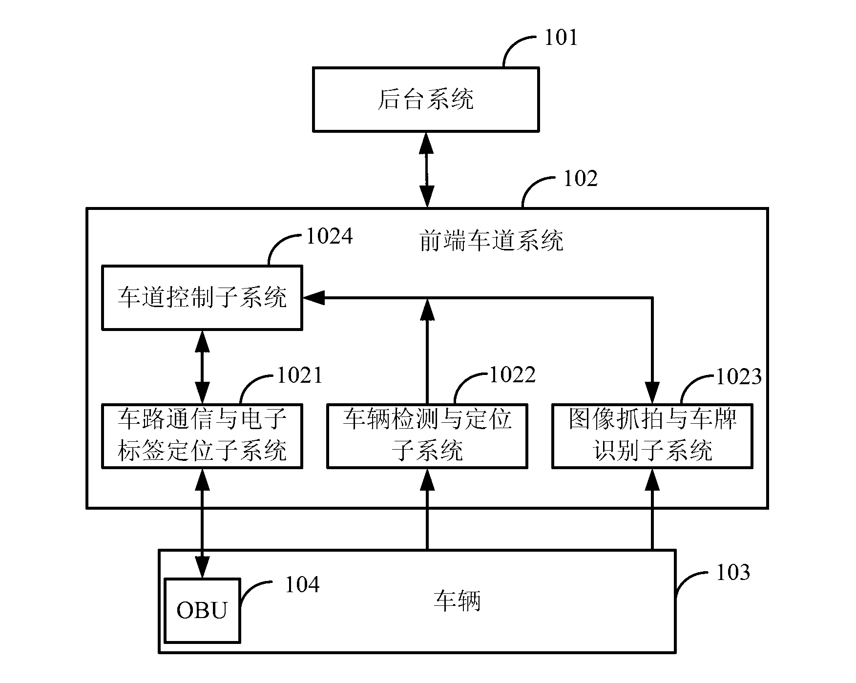
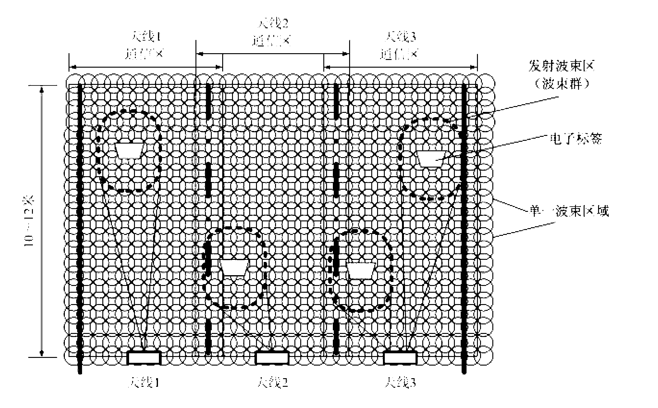
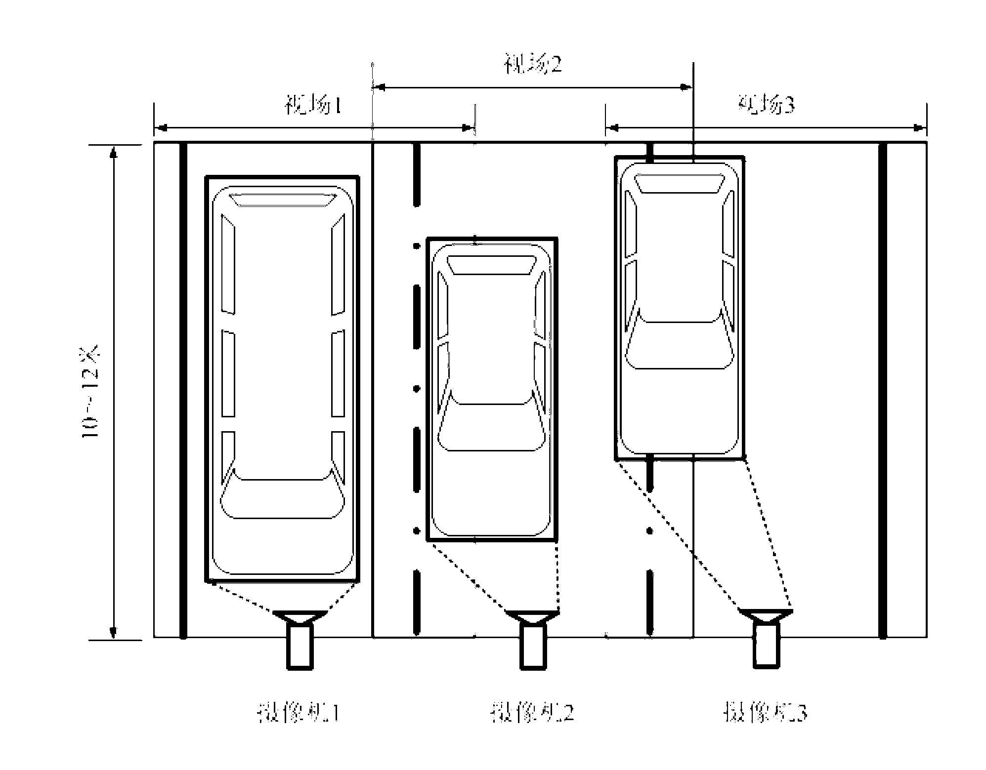
[0086] The schematic diagram of the installation and working principle of the front-end lane system equipment in this embodiment is as follows Figure 4 As shown, this scheme is a double-gantry lane layout, in which vehicles drive from left to right, rear vehicle capture and license plate recognition cameras 403 are installed on gantry A, and multi-beam antennas 407 and video track tracking systems are installed on gantry B 409 and front vehicle capture and license plate recognition camera 408. In this embodiment, the vehicle-road communication and electronic tag positioning subsystem is mainly composed of three lanes of multi-beam antennas, and the three antennas simultaneously transmit and receive signals to achieve full coverage of the lane communication area. The vehicle detection and positioning subsystem is mainly composed of high-speed high-definition cameras, whic...
Embodiment 2
[0101] Embodiment 2: Quasi-multi-lane free-flow lane layout based on license plate matching
[0102] The schematic diagram of the installation and working principle of the front-end lane system equipment in this embodiment is as follows Figure 5As shown, this scheme is a lane layout of double gantry frames, wherein vehicles drive from left to right, gantry A is equipped with rear vehicle capture and license plate recognition camera 503, and gantry B is equipped with front vehicle capture and license plate recognition camera 507 and multi-beam antenna 506 . In this embodiment, the vehicle-road communication and electronic tag positioning subsystem is mainly composed of three lanes of multi-beam antennas, and the three antennas simultaneously transmit and receive signals to achieve full coverage of the lane communication area. The vehicle detection and positioning subsystem is mainly composed of the ground sensing coil 508, which is responsible for detecting the vehicle's driv...
Embodiment 3
[0117] Example 3: Multi-lane free-flow lane layout based on license plate auxiliary position matching
[0118] The schematic diagram of the installation and working principle of the front-end lane system equipment in this embodiment is as follows Figure 6 As shown, this scheme is a three-gantry lane layout, in which vehicles drive from left to right, rear vehicle capture and license plate recognition cameras 603 are installed on gantry A, and vehicle detection equipment such as laser curtain wall 604 and gantry B are installed on gantry B. A front vehicle capture and license plate recognition camera 608 and a multi-beam antenna 607 are installed on the frame C. In this embodiment, the vehicle-road communication and electronic tag positioning subsystem consists of three multi-beam antennas as the core equipment, and the three antennas simultaneously transmit and receive signals to achieve full coverage of the lane communication area. The vehicle detection and positioning subs...
PUM
 Abstract
Description
Claims
Application Information
 - R&D
- Intellectual Property
- Life Sciences
- Materials
- Tech Scout
- Unparalleled Data Quality
- Higher Quality Content
- 60% Fewer Hallucinations
Browse by: Latest US Patents, China's latest patents, Technical Efficacy Thesaurus, Application Domain, Technology Topic, Popular Technical Reports.
© 2025 PatSnap. All rights reserved.Legal|Privacy policy|Modern Slavery Act Transparency Statement|Sitemap|About US| Contact US: help@patsnap.com


