Drainage structure of planted roof

A technology of roof drainage structure and roof structure layer, applied in the direction of roof drainage, roof, roof covering layer, etc., can solve the problems of increasing project cost, easy blockage of rainwater bucket, inconvenient maintenance and dredging, etc., to save project cost and reduce Quantity, the effect of reducing the probability of roof leakage

Active Publication Date: 2015-02-25
SHENZHEN GENERAL INST OF ARCHITECTURAL DESIGN & RES
View PDF4 Cites 1 Cited by
  • Summary
  • Abstract
  • Description
  • Claims
  • Application Information

AI Technical Summary

Problems solved by technology

[0003] The above rainwater drainage methods for planted roofs have the following problems: (1) Surface runoff rainwater and infiltration rainwater are discharged through different rainwater buckets, which increases the number of rainwater buckets passing through the roof panels and increases the project cost. risk of water leakage
(2) The rainwater bucket installed on the surface layer of the roof, because there are flowers, plants and trees on the roof, the surface rainwater runoff will carry dead branches, fallen leaves and sediment, which will easily cause the rainwater bucket to be blocked, especially when the rainwater bucket adopts a siphon rainwater bucket. The grid spacing of the siphon rainwater bucket is small, and this kind of rainwater bucket is more likely to be blocked
(3) The rainwater bucket installed under the planting soil is a concealed installation, which is not convenient for maintenance and dredging

Method used


Image

  • Drainage structure of planted roof
  • Drainage structure of planted roof
  • Drainage structure of planted roof

Examples


Embodiment Construction

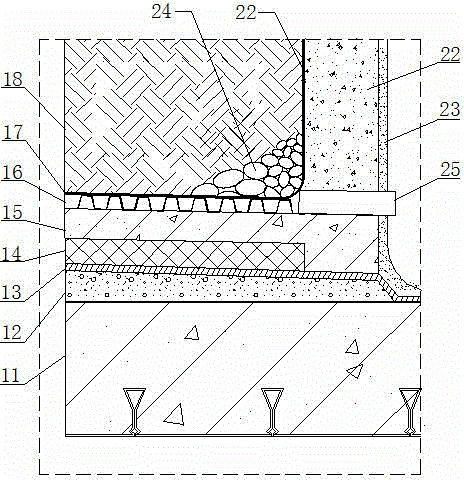
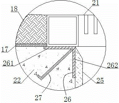
[0022] In the present invention, the terms "upper", "lower", "left", "right", "front", "rear", "top", "bottom", "inner", "outer", "middle", The orientations or positional relationships indicated by "vertical", "horizontal", "horizontal", and "longitudinal" are based on the orientations or positional relationships shown in the drawings. These terms are mainly used to better describe the present invention and its embodiments, and are not intended to limit that the indicated device, element or component must have a specific orientation, or be constructed and operated in a specific orientation.

[0023] Moreover, some of the above terms may be used to indicate other meanings besides orientation or positional relationship, for example, the term "upper" may also be used to indicate a certain attachment relationship or connection relationship in some cases. Those skilled in the art can understand the specific meanings of these terms in the present invention according to specific situ...


PUM


Abstract

The invention relates to building roof structure s, in particular to a drainage structure of a planted roof. The drainage structure of the planted roof comprises a roof structure layer, a plant soil layer directly or indirectly arranged on the roof structure layer, a water drainage opening formed in the plant soil layer, a rainwater hopper connected at the bottom of the water drainage opening and inlaid in the roof structure layer, and a water drainage pipe for communicating the plant soil layer with the water drainage opening so as to drain infiltrating water in the plant soil layer to the water drainage opening, wherein the water drainage opening is formed by surrounding of a well wall on the roof structure layer. By the drainage structure of the planted roof, overland flows on the planted roof and the infiltrating water under plant oil on the planted roof can be converged and drained together with rainwater, so that the number of the rainwater hoppers is decreased, engineering cost is saved, and roof leakage probability is decreased.

Description

technical field [0001] The invention relates to a building roof structure, in particular to a drainage structure arranged on a planting roof. Background technique [0002] At present, the drainage of planted roofs is mainly carried out by combining two methods. One is that the runoff rainwater on the surface of the planted roof passes through the slope of the building to the rainwater bucket or rainwater ditch on the surface of the roof. The second is that the rainwater infiltrated into the planting soil of the planting roof seeps through the drainage board or the porous drainage pipe to the rainwater culvert on the roof structure plate under the planting soil. There is a rainwater hopper in the rainwater culvert, and the infiltrating rainwater finally passes through the rainwater bucket ruled out. [0003] The above rainwater drainage methods for planted roofs have the following problems: (1) Surface runoff rainwater and infiltration rainwater are discharged through differ...

Claims


Application Information

Patent Timeline
Patent Type & Authority Patents(China)
IPC IPC(8): E04D13/04E04D13/076E04D11/02
CPCY02A30/254Y02B80/32
Inventor 郑文星
Owner SHENZHEN GENERAL INST OF ARCHITECTURAL DESIGN & RES
Why Eureka
Try Eureka