A self-generating electric vehicle controller
A technology of electric vehicle controller and electric energy controller, which is applied to terminal battery switching devices and other directions, can solve problems such as short mileage, and achieve the effect of reducing the number of charging times, increasing the discharge cycle, and improving the mileage.
- Summary
- Abstract
- Description
- Claims
- Application Information
AI Technical Summary
Problems solved by technology
Method used
Image
Examples
Embodiment 1
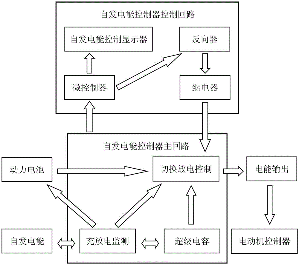
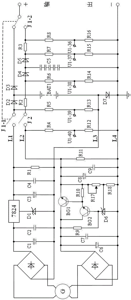
[0032] Depend on figure 2 It can be seen that the main loop circuit of the present invention is composed of three parts: switching discharge control, charging and discharging monitoring and energy storage, wherein
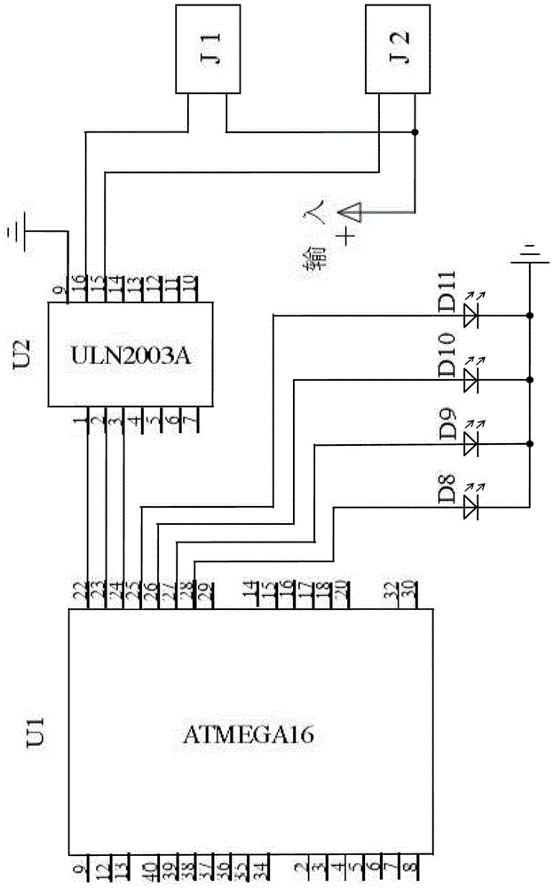
[0033] The switching discharge control part is composed of a relay switch, a power battery and a super capacitor. The self-generated energy generated by the generator G is output in two ways, of which the line L1 and the line L3 are the first line, and the line L2 and the line L4 are the second line. L1 and L2 are positive poles, L3 and L4 are negative poles. The first path is rectified and filtered by capacitor C1, and then the voltage stabilizing block 7824 generates a regulated power supply that can charge the power battery BAT1. The second path is rectified and filtered. A constant voltage source composed of regulator tube D6, resistor R18 and potentiometer R17 provides a reference voltage for the base of BG2 to obtain a regulated power supply that can charge ...
Embodiment 2
[0040] Depend on Figure 4 It can be seen that the main loop circuit of the present invention is composed of three parts: switching discharge control, charging and discharging monitoring and energy storage, wherein
[0041] The switching discharge control part is composed of a relay switch, a power battery and a supercapacitor. The self-generated energy generated by the generator G is output in two ways, of which the line L5 and the line L7 are the first line, and the line L6 and the line L8 are the second line. L5 and L6 are positive poles, L7 and L8 are negative poles. After the first circuit is rectified and filtered by capacitor C1, the voltage stabilizing block 7824 generates a regulated power supply that can charge the battery BAT1. A constant voltage source composed of a voltage tube D6, a resistor R18 and a potentiometer R17 provides a reference voltage for the base of BG2 to obtain a regulated power supply that can charge supercapacitors C10 and C11, where the line L5...
PUM
 Abstract
Description
Claims
Application Information
 - R&D
- Intellectual Property
- Life Sciences
- Materials
- Tech Scout
- Unparalleled Data Quality
- Higher Quality Content
- 60% Fewer Hallucinations
Browse by: Latest US Patents, China's latest patents, Technical Efficacy Thesaurus, Application Domain, Technology Topic, Popular Technical Reports.
© 2025 PatSnap. All rights reserved.Legal|Privacy policy|Modern Slavery Act Transparency Statement|Sitemap|About US| Contact US: help@patsnap.com


