A general hydraulic station energy saving method

A technology of hydraulic station and hydraulic energy storage, which is applied in the direction of fluid pressure actuation device, fluid pressure actuation system components, mechanical equipment, etc., and can solve the problems of low reliability and safety, small scope of application, limited scope of use, etc. problems, to achieve the effect of improving system reliability and maintainability, high security redundancy, and broadening the scope of use

Inactive Publication Date: 2016-12-21
上海艾科液压技术有限公司
View PDF3 Cites 0 Cited by
  • Summary
  • Abstract
  • Description
  • Claims
  • Application Information

AI Technical Summary

Problems solved by technology

[0005] Existing patent: 200610050558.6 "Energy saving method for hydraulic station of stainless steel strip pickling continuous annealing production line" discloses a hydraulic station, which is only suitable for stainless steel strip pickling continuous annealing production line, and the scope of application is very small; only specific The empirical formula of the unit, the scope of use is greatly limited
[0006] In addition, although the patented technology of "Hydraulic energy-saving motor" is energy-saving, it is not suitable for use in high-reliability occasions that require high system pressure stability and large changes in load flow requirements, so its application range is actually very limited, and its fast response The reliability is seriously limited by the pressure drop of the system, so it can only be used in some occasions where the reliability and safety are not high
"Hydraulic energy-saving motor" Compared with the existing hydraulic energy-saving technology of "accumulator pressure maintenance-working pump stop-working pump (when pressure drops) restart", hydraulic energy saving is not obvious; moreover, the accumulator needs to be extended The pressure holding time and reducing the start-up frequency of the pump can be easily solved by increasing the installed capacity of the accumulator, and this technology has obvious logical errors in the structure, and it is difficult to have specific use value

Method used


Image

  • A general hydraulic station energy saving method
  • A general hydraulic station energy saving method
  • A general hydraulic station energy saving method

Examples


Embodiment Construction

[0038] The utility model is described in further detail below in conjunction with the accompanying drawings.

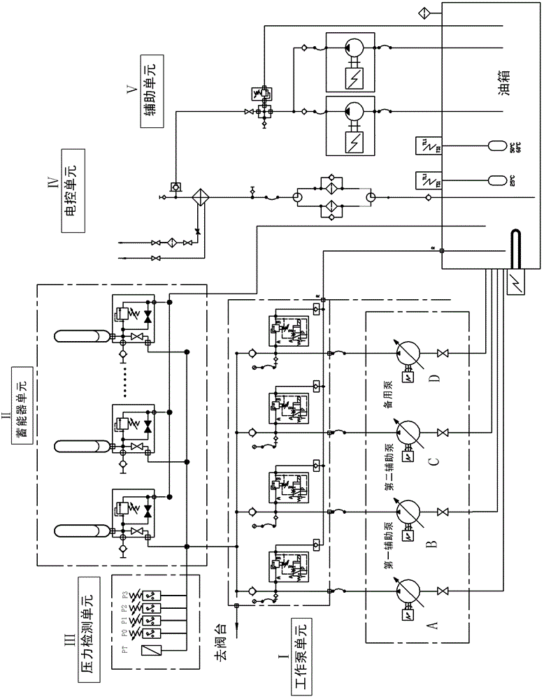
[0039] like figure 1 Shown is a preferred embodiment of the present invention.

[0040] A general energy-saving method for a hydraulic station, including a working pump I, a hydraulic energy storage station II, a pressure detection unit III, and an electric control unit IV; And the hydraulic energy storage station II provides the main flow and pressure and the flow required to maintain the internal and external leakage of the system. Among them, the main pump is in normal operation, and the auxiliary pump is controlled by the signal detected by the pressure detection unit III and controlled by the electronic control unit IV.

[0041] The system electronic control unit IV is the same as every hydraulic station now, the electronic control unit is essential, the start and stop of the driving motor and the loading or unloading of the pump are all realized by its software...


PUM


Abstract

The invention relates to a universal hydraulic station energy-saving method which comprises a working pump, a hydraulic energy storage station, a pressure detecting unit and an electric control unit. The working pump comprises a main pump and an auxiliary pump for working and is used for providing main flow and pressure for a hydraulic actuator and the hydraulic energy storage station and maintaining flow needed by internal and external leakage of a system, the main pump frequently runs, the auxiliary pump is controlled to start or stop through the electric control unit by the aid of a signal detected by the pressure detecting unit, the pressure detecting unit is provided with a plurality of pressure parameter points, and a certain formula relationship among the pressure parameter points is met. By the aid of the universal hydraulic station energy-saving method, the best energy-saving effect can be achieved, reliability of a hydraulic station is sufficiently guaranteed, the hydraulic station has a certain self-diagnosis function, flow or energy output of the hydraulic station is high in load following performance and adaptivity, and reliability and the use ratio of hydraulic station energy are effectively and coordinately improved. The method is maximally characterized in that actual hydraulic energy requirements in a product cycle of system unit production serve as a design reference, and the method is fundamentally different from a traditional mode that the maximum external acting output power of a hydraulic system serves as a design reference.

Description

technical field [0001] The invention relates to a general hydraulic station structure and its energy-saving method. The hydraulic station is suitable for hydraulic energy-saving technologies in all light and heavy industries except walking machinery. It is a general-purpose energy-saving hydraulic station that can be widely used. The energy-saving design of the hydraulic station is suitable for the energy-saving transformation of the old hydraulic station. Background technique [0002] Although the current hydraulic system has widely used energy-saving methods such as constant pressure variable pumps, accumulator pressure maintenance-pump unloading and no-load-pressure detection and restarting; but the energy consumption is still very high, and the effective utilization rate of energy is generally 20%. Below, some are even below 5%. The root cause of high energy consumption is that the hydraulic pump (motor) has a large installed capacity and the motor has high energy consu...

Claims


Application Information

Patent Timeline
Patent Type & Authority Patents(China)
IPC IPC(8): F15B21/00
Inventor 何荣志
Owner 上海艾科液压技术有限公司
Why Eureka
Try Eureka