Interphase short circuit fault relay protection method of transmission line

A transmission line, interphase short-circuit technology, applied in emergency protection circuit devices, electrical components, etc., can solve problems such as load transfer, power grid security safety hazards, and traditional distance protection malfunctions.

Active Publication Date: 2016-01-20
STATE GRID CORP OF CHINA +2
View PDF4 Cites 0 Cited by
  • Summary
  • Abstract
  • Description
  • Claims
  • Application Information

AI Technical Summary

Problems solved by technology

[0002] The additional impedance generated by the transition resistance will seriously affect the action performance of the impedance distance protection
If the additional impedance generated by the transition resistance is resistive and inductive, it is easy to cause the impedance distance protection to refuse to operate when there is a short-circuit fault between phases in the protection zone; The distance protection action produces overtaking
[0003] High / super / extreme voltage AC transmission lines are often also heavy-duty transmission lines. Heavy-load currents will cause the impedance distance protection to malfunction or refuse to operate. The influence of heavy-load currents on the performance of impedance distance protection cannot be ignored.
Under the condition of overload transmission, the line operates normally. The measured impedance of the traditional impedance distance protection will seriously deviate from the actual measured impedance due to the influence of the overload current, which will easily lead to the misoperation of the traditional distance protection, resulting in the expansion of the power grid blackout range, and even causing a large number of load transfers to threaten the line. Normal operation has caused a huge security risk to the power grid

Method used


Image

  • Interphase short circuit fault relay protection method of transmission line
  • Interphase short circuit fault relay protection method of transmission line
  • Interphase short circuit fault relay protection method of transmission line

Examples


Embodiment Construction

[0018] The technical solution of the present invention will be further described in detail below according to the drawings of the specification.

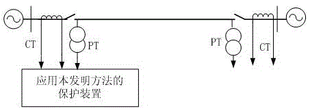
[0019] figure 1 This is a schematic diagram of the line transmission system applying the present invention. figure 1 PT is a voltage transformer, and CT is a current transformer. The protection device samples the voltage waveform of the voltage transformer PT and the current waveform of the current transformer CT at the transmission line protection installation to obtain the instantaneous values ​​of voltage and current, and uses the Fourier algorithm to calculate the fault phase-to-phase voltage at the transmission line protection installation. Fault phase current Negative sequence current between phase and fault Among them, φφ=AB, BC, CA phase.

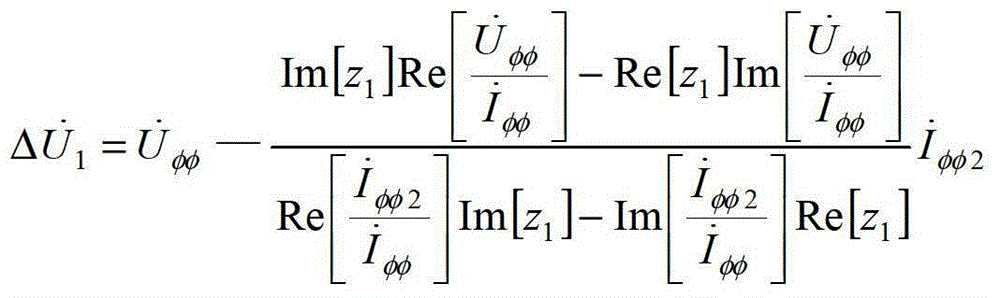
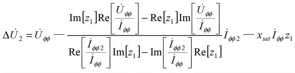
[0020] The protection device calculates the voltage drop from the protection installation of the transmission line to the phase-to-phase short-circuit fault point

[0021] Δ U ·...


PUM


Abstract

The invention discloses a relay protection method for interphase short circuit faults of an electric transmission line. The relay protection method comprises the following steps: a voltage drop from an electric transmission line protection mounting part to an interphase short circuit fault point and a voltage drop from an electric transmission line protection setting range to the interphase short circuit fault point are calculated by using fault interphase electrical capacity at the electric transmission line protection mounting part, and if the angle between the voltage drop from the electric transmission line protection mounting part to the interphase short circuit fault point and the voltage drop from the electric transmission line protection setting range to the interphase short circuit fault point ranges from 90 degrees to 270 degrees, an action tripping signal is given out by a protection device. The method solves the problem of the influence of transition resistance and load current on the protection action performance, and when interphase high-resistance short circuit faults occur to the electric transmission line, the method can act correctly and reliably, the action sensitivity is high, and the protection range is stable.

Description

Technical field [0001] The invention relates to the technical field of power system relay protection, in particular to a relay protection method for short-circuit faults between phases of transmission lines. Background technique [0002] The additional impedance generated by the transition resistance will seriously affect the performance of the impedance distance protection. If the additional impedance generated by the transition resistance is resistive and inductive, it is easy to cause the impedance distance protection to refuse to operate when the phase-to-phase short-circuit fault occurs in the protection zone; if the additional impedance generated by the transition resistance is resistive-capacitive, it will easily cause the impedance when the phase-to-phase short-circuit fault occurs outside the protection zone. The distance protection action produces overreach. [0003] High / super / extra-voltage AC transmission lines are often heavy-duty transmission lines. Heavy-load curren...

Claims


Application Information

Patent Timeline
Patent Type & Authority Patents(China)
IPC IPC(8): H02H7/26
Inventor 林富洪
Owner STATE GRID CORP OF CHINA
Why Eureka
Try Eureka