
Retractable circuit detection pen

A circuit detection and electric prod technology, which is applied to measuring devices, measuring electrical variables, measuring current/voltage, etc., can solve the problems of large size and inconvenient carrying of electric pens, and achieve the effects of easy portability, simple structure and convenient use.

Inactive Publication Date: 2013-08-14
林伟良
View PDF0 Cites 1 Cited by
  • Summary
  • Abstract
  • Description
  • Claims
  • Application Information

AI Technical Summary

Benefits of technology

This new type of device with an easy-to-use feature can be used for detecting circuits without having any extra parts or tools attached that make it difficult to carry around them easily.

Problems solved by technology

This patented technical problem addressed in this patents relates to making smaller electronic devices easier for people who want them charging things up quickly without having too much space on their hands.

Method used


Image

  • Retractable circuit detection pen

Examples


Embodiment Construction

[0011] The preferred embodiments of the present invention will be described in detail below in conjunction with the accompanying drawings, so that the advantages and features of the present invention can be more easily understood by those skilled in the art, so as to define the protection scope of the present invention more clearly.

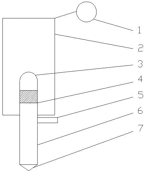
[0012] see figure 1 , a retractable circuit detection pen, comprising: a retractable electric rod 6, a resistance block 4, an insulating casing 2, a nib 7, a neon bulb 3 and a switch 5, the retractable electric rod 6 and the resistance block 4 are electrically connected together, the The top of the telescopic electric rod 6 is connected with a neon bulb 3, the bottom of the telescopic electric rod 6 is a nib 7, the telescopic electric rod 6 is installed inside the insulating shell 2, and the connection between the telescopic electric rod 6 and the insulating shell 2 is equipped with The switch 5 is connected with the neon bulb 3 and the resistanc...


PUM


Abstract

The invention discloses a retractable circuit detection pen which comprises a retractable electric rod, a resistance block, an insulating housing, a pen point, a neon bulb and a switch, wherein the retractable electric rod is electrically connected together with the resistance block; the top end of the retractable electric rod is connected with the neon bulb; the pen point is positioned at the bottom of the retractable electric rod; the retractable electric rod is mounted in the insulating housing; the switch is mounted at the joint of the retractable electric rod and the insulating housing; and the neon bulb is in built-up connection with the resistance block. With the scheme, the retractable circuit detection pen provided by the invention is simple in structure and convenient to use, has a retractable pen holder and is portable.

Description


Claims


Application Information

Patent Timeline
Owner 林伟良
Learn More