Mechanical lock

A technology of mechanical locks and lock cylinders, applied in the field of mechanical locks, can solve the problems of low explosion-proof lock breaking ability and professional technology lock breaking ability, high cost of locks, complicated manufacturing, etc., to eliminate technical unlocking, strong anti-theft opening performance, The effect that there are few lock parts

Inactive Publication Date: 2013-08-14
肖立忠
View PDF4 Cites 4 Cited by
  • Summary
  • Abstract
  • Description
  • Claims
  • Application Information

AI Technical Summary

Problems solved by technology

This technology has been used for 165 years since the American L. Yale invented the cylindrical pin mechanical lock in 1848, but the ability to break the lock with explosion-proof force and professional technology is not strong; in order to improve the anti-theft function and confidentiality, in the lock industry, people have worked hard to create electronic locks, smart locks, combination locks, etc. These locks are expensive, and they are not easy to repair if they are broken, and ordinary people cannot accept them.
Therefore, people still optimize the lock invented by L. Yale, but they only work hard on the new and complex level, so that the key technology of the main part of the lock cylinder and the lock body cannot be upgraded, and it evolves from a short lock cylinder. Into a super-long lock core, from one lock core to more than two lock cores, that is, an inner lock core with a key hole is installed in the round hole-shaped lock core hole of the lock core body, and a key hole is arranged in the inner lock core. There are pinholes that pass through the key hole and the outer surface of the inner lock cylinder, and there are pinholes corresponding to the pinholes of the inner lock cylinder in the lock cylinder body, and each of the butted pinholes of the inner lock core and the lock core body is equal to the pinhole. Two cylindrical pins are installed, and a spring acting on the pins is installed in the pin hole of the outer lock core. When the key is inserted into the key hole of the inner lock core, the teeth with different heights are set on the key just to align the key hole. The outer end of the inner marble is driven to the hole surface where the inner lock cylinder and the lock cylinder body are joined, so that the inner lock cylinder can rotate relative to the lock cylinder body to drive the lock to unlock; when the matched key exits the inner lock cylinder or an illegal key is inserted into the inner lock cylinder When the keyhole of the lock cylinder is in the key hole, due to the action of the spring in the pinhole, the joint surfaces of the two pinholes in each pinhole cannot be aligned with the joint surface of the lock cylinder body and the inner lock cylinder, resulting in at least one pinhole. If the locking of the lock cylinder body and the inner lock cylinder is realized by being stuck in this joint surface, although the cracking probability of such a lock is more difficult, such a lock has many parts and is complicated to manufacture, resulting in high cost and difficult maintenance

Method used


Image

  • Mechanical lock
  • Mechanical lock
  • Mechanical lock

Examples


Embodiment Construction

[0019] The present invention will be described in further detail below in conjunction with accompanying drawing example:

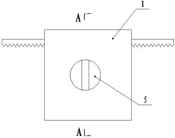
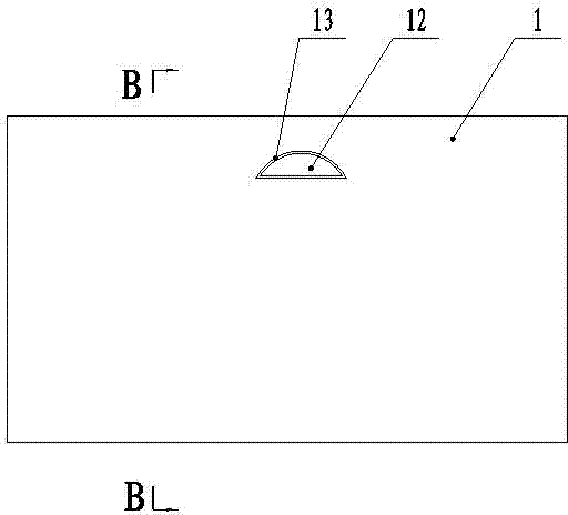
[0020] Such as Figure 1-Figure 4 The present invention shown, it comprises lock body 1 and is provided with the lock core 2 of key hole, and lock core 2 is contained in the slideway 3 of lock body 1, and lock core 2 is a hollow cylinder, and this lock core middle part is along The axial direction is provided with a barrier 4, which divides the inner cavity of the lock cylinder 2 into two symmetrical halves, wherein one side of the inner cavity is the key hole 5 outside the door, and the other port of the key hole outside the door is provided with a block; The inner cavity is the key hole 6 in the door, and the other port of the key hole in the door is also provided with a block, and a positioning snap ring 17 is crimped between the edge of the outer end of the lock core and the lock body 1, and the lock core 2 is connected from the lock body After the ou...


PUM


Abstract

The invention discloses a mechanical lock and relates to the technical field of lock manufacturing. The mechanical lock comprises a lock body and a lock cylinder, wherein the lock cylinder is installed in a sliding way in the lock body, the lock cylinder is a hollow tube, a baffle is arranged in the middle of the lock cylinder in the axis direction and divides an inner cavity of the lock cylinder into two symmetrical halves, lock pin sliding ways with even numbers are arranged on the baffle and are symmetrically arranged towards two sides of the baffle with the central point of the baffle in the length direction as the basic point, and lock pins are installed in the lock pin sliding ways. A plurality of lock pin inserting grooves butting against external ports of the plurality of lock pin sliding ways in the lock cylinder when the lock cylinder rotates to the locking position in the sliding ways are arranged on the lock body, and the lock pin inserting grooves are symmetrically arranged with the central points of the sliding ways as the basic point. The lock pins are in a '+' shape, and transverse edges of the lock pins extend out from two sides of the baffle. A gear is sleeved on the middle section of the lock cylinder, the gear is installed in a gear groove on the lock body, the gear is meshed with a rack, and two ends of the rack extends out from rack holes on two sides of the lock body. The mechanical lock requires fewer parts and is strong in illegal unlocking prevention capability.

Description

technical field [0001] The invention relates to the technical field of lock manufacturing, in particular to a mechanical lock which has a lock body and a lock core and can be opened with a key. Background technique [0002] Lock is a tool widely used in anti-theft and security. Historically, it has taken a hundred years for one type of lock to be replaced by another more advanced lock. This technology has been used for 165 years since the American L. Yale invented the cylindrical pin mechanical lock in 1848, but the ability to break the lock with explosion-proof force and professional technology is not strong; in order to improve the anti-theft function And confidentiality, in the lock industry, people have worked hard to create electronic locks, smart locks, combination locks, etc. These locks are expensive, and they are not easy to repair if they are broken, and ordinary people cannot accept them. Therefore, people still optimize the lock invented by L. Yale, but they onl...

Claims


Application Information

Patent Timeline
IPC IPC(8): E05B23/00E05B15/14E05B63/00
Inventor 肖立忠
Owner 肖立忠
Why Eureka
Try Eureka