
Power and steering device for crawler-type harvester

A technology of steering device and harvester, which is applied in the direction of harvester, agricultural machinery and implements, etc. It can solve the problems of laborious steering, inability to replace tracks with tires, and cumbersome height adjustment, so as to reduce production costs, improve production efficiency, low cost effect

Active Publication Date: 2015-02-25
CHONGQING SHINERAY AGRI MACHINERY
View PDF10 Cites 0 Cited by
  • Summary
  • Abstract
  • Description
  • Claims
  • Application Information

AI Technical Summary

Problems solved by technology

If it is applied to a crawler-type harvester, since the crawlers are generally triangular or square and have a large ground area, steering is laborious, and it is often necessary to push one of the crawlers manually to achieve steering, which is time-consuming and laborious.
[0004] Harvesters in the prior art have a complex crawler structure, a large ground area, heavy weight, and laborious steering; moreover, there is basically no interchangeability between the crawlers and tires, that is, the crawlers cannot be quickly replaced with tires when needed , or replace the wheels with crawlers to meet the requirements of different road surfaces and different working conditions
[0005] During the working process of the harvester, in order to adapt to different grounds, terrain environments, and operators of different heights, it is necessary to adjust the height of the harvester itself, so that the operator can save time and effort when driving the harvester and operate efficiently; however, the existing The harvester in the technology is cumbersome to adjust its own height, which is very inconvenient, and the structure is complicated, which cannot meet the actual needs of users

Method used


Image

  • Power and steering device for crawler-type harvester
  • Power and steering device for crawler-type harvester
  • Power and steering device for crawler-type harvester

Examples


Embodiment Construction

[0025] The present invention will be further described below in conjunction with the accompanying drawings and embodiments.

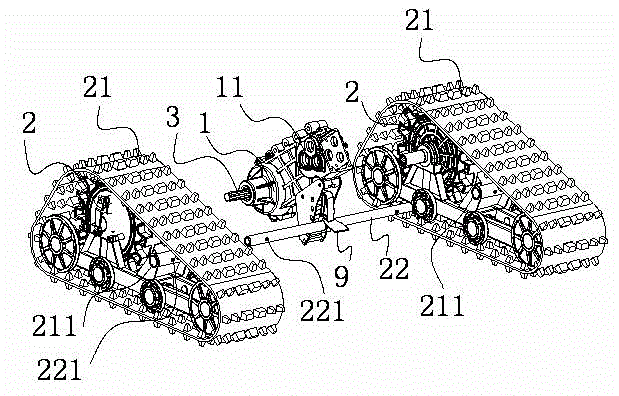
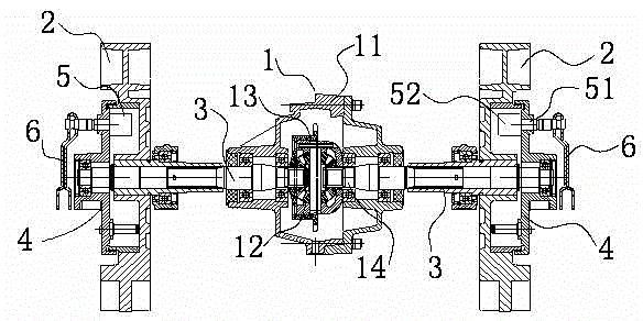
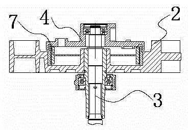
[0026] The power and steering device of the crawler harvester provided by this embodiment, such as figure 1 , figure 2 , 3 , 4, 5, and 6, it includes a transmission 1, two left and right drive wheel assemblies 2 arranged on both sides of the transmission 1 and two left and right output axle shafts 3, and the transmission 1 includes a transmission case 11 1. The differential 12 installed in the transmission case 11 and the power input structure 13 sleeved on one side of the differential 12, one end of the left and right output axle shafts 3 are respectively connected to the differential 12, and the other One end is respectively connected with the left and right two drive wheel assemblies 2 to drive the left and right drive wheel assemblies 2 to rotate, and the left and right drive wheel assemblies 2 then respectively drive the left and right crawl...


PUM


Abstract

The invention discloses a power and steering device for a harvester. The power and steering device comprises a transmission, a left driving wheel assembly, a right driving wheel assembly, a left output half shaft and a right output half shaft, wherein the left driving wheel assembly, the right driving wheel assembly, the left output half shaft and the right output half shaft are arranged on two sides of the transmission. Each driving wheel assembly is provided with a friction braking assembly, and each friction braking assembly comprises a brake end cover, a tensioning cam arranged on the brake end cover and a pull cable rotating arm connected with the tensioning cam, wherein the tensioning cam is composed of a rotating rod and a protruded block which are connected with each other. The driving wheel assemblies are provided with annular brake shoes matched with the protruded blocks. When the tensioning cam rotates axially, the protruded blocks drive the brake shoes to expand so as to contact with the inner sides of the driving wheel assemblies, and braking frictional resistance is generated. The power and steering device for the harvester can achieve automatic steering, and the steering radius is small.

Description

technical field [0001] The invention relates to a power and steering device of agricultural equipment, in particular to a power and steering device of a crawler-type agricultural crawler harvester. Background technique [0002] With the development of science and technology, many places now use agricultural equipment to sow and harvest crops. Among them, harvesters are divided into half-feed harvesters and full-feed harvesters. The form of the harvester can be divided into wheel type and crawler type. At present, because of its good grip and high friction, crawler harvesters can also be used in mountainous areas with relatively harsh environments. Therefore, they are often used in relatively harsh terrains. [0003] When using the harvester, because the harvester is relatively heavy, it is troublesome to turn. In order to solve the above problems, the State Intellectual Property Office of China announced on October 3, 2012, a small-scale walking agricultural machine steer...

Claims


Application Information

Patent Timeline
Patent Type & Authority Patents(China)
IPC IPC(8): A01D69/06
Inventor 汪仁凡秦大国李川
Owner CHONGQING SHINERAY AGRI MACHINERY
Learn More