Pipe bursting apparatus

一种地下管、安装杆的技术,应用在管元件、管子/管接头/管件、钻孔设备和方法等方向,能够解决体力困难、复杂、增加制造成本等问题

Inactive Publication Date: 2013-07-24
罗伯特·沃德·卡特尔 +1
View PDF1 Cites 2 Cited by
  • Summary
  • Abstract
  • Description
  • Claims
  • Application Information

AI Technical Summary

Problems solved by technology

[0007] However, tube rupture devices in smaller applications are still relatively large, heavy and complex
Therefore, it is physically difficult to operate such a device, and the material and manufacturing costs are considerable
At the same time, due to the large pulling force required in the pulling process, high-pressure hydraulic devices are often used, which further increases the manufacturing cost

Method used


Image

  • Pipe bursting apparatus
  • Pipe bursting apparatus
  • Pipe bursting apparatus

Examples


Embodiment Construction

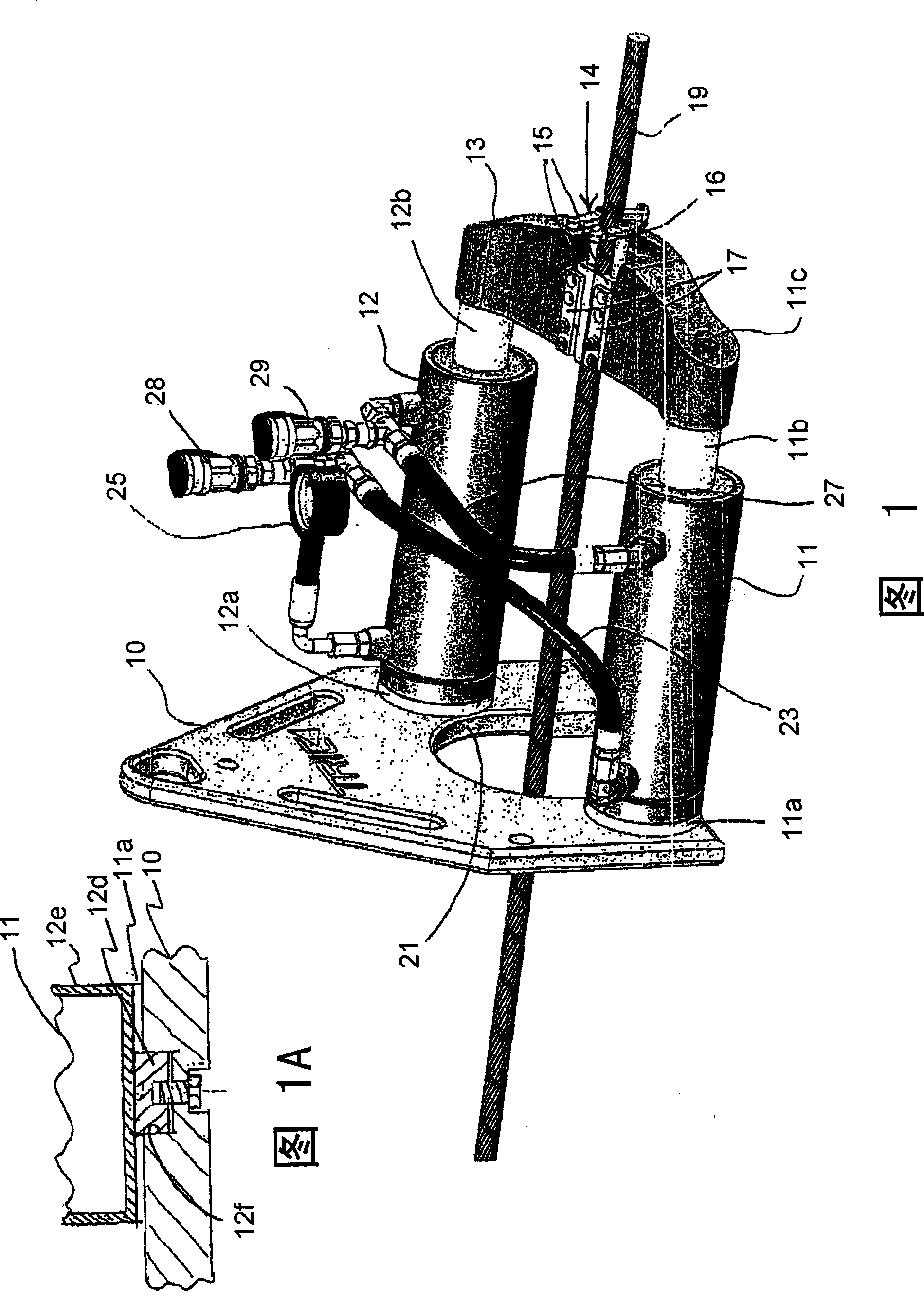
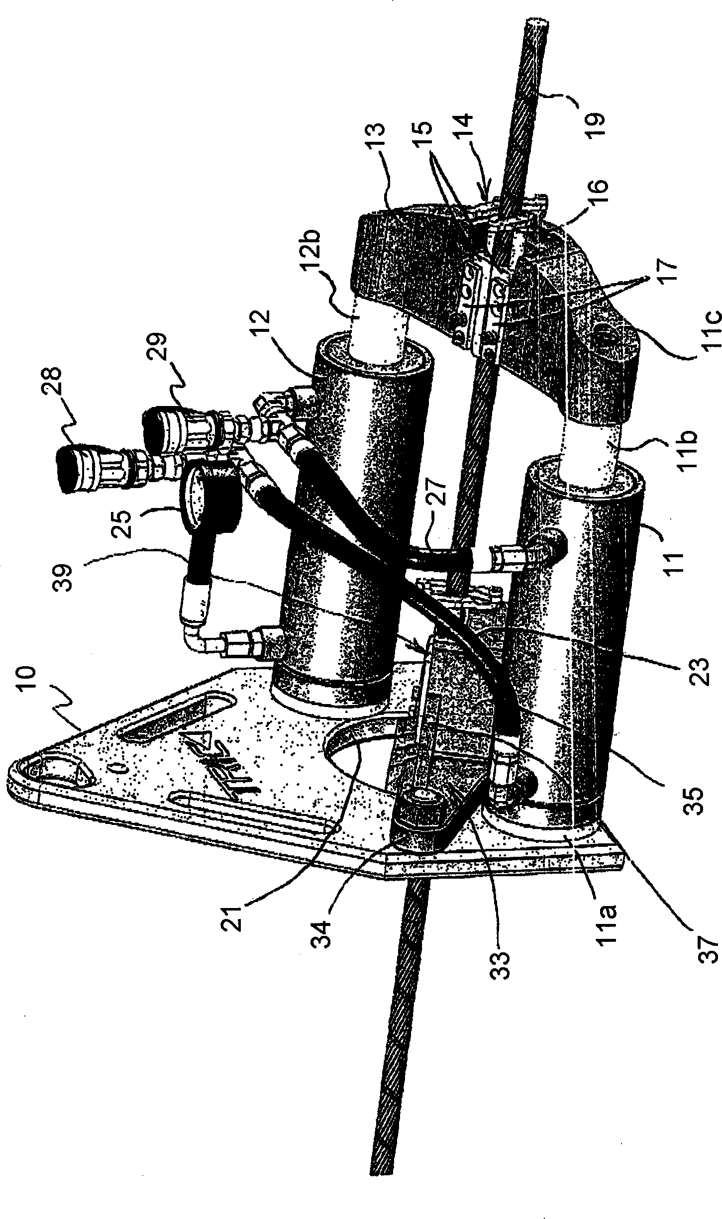
[0014] see figure 1 and 2 , describes a preferred form of the device of the invention. The reaction plate 10, also known as the drag plate, is preferably 18 to 24 inches wide, about the same size in height, and one to two inches thick. The reaction plate 10 is preferably steel or similar material. The reaction plate is positioned within a well at one end of the pipe section being replaced to bear against the wall of the well from which the pipe section normally emerges. Wood or equivalent material may be placed between the reaction plate and the pit walls as desired to distribute the load. In any event, the reaction plate supports the other components of the device as will be described. As shown, the reaction plate may have unnumbered openings for ease of handling and weight reduction.

[0015] The reaction plate 10 is also provided with another opening or slot 21 to allow the pull cable 19 to pass through the reaction plate. Because the slot 21 runs through one side of...


PUM


Abstract

Apparatus for replacing underground pipe is described, including a resistance plate from which a pair of hydraulic cylinders extend perpendicularly parallel with each other. The cylinders operate cyclically with a pulling bridge having a cable gripper to provide a sequence of pulling strokes to a cable pulling a mole. The mole pulls a replacement pipe behind it through the old pipe, which has been burst, slit, or expanded by the mole. The resistance plate is provided with a slot, and the cylinders are positioned to allow the mole to be pulled substantially completely into the apparatus. A holding bridge is releasably mounted spanning the slot in the reaction plate to position a second cable gripper for holding the cable on the return stroke of the pulling bridge. The holding bridge may be removed at the end of the pulling operation to accommodate the mole. A robust, lightweight construction is described.

Description

[0001] Cross References to Related Applications [0002] This application claims the benefit of US Provisional Application No. 61 / 458,981 filed December 3, 2010, which is incorporated herein by reference in its entirety. technical field [0003] This invention relates to the replacement of underground pipes using what is known as a pipe rupture device. In particular, the present invention relates to an improved apparatus for replacing underground pipe by rupturing or splitting the pipe in situ while pulling the replacement pipe to substantially the same position. Background technique [0004] Pipe rupture technology is a known technique for replacing underground pipes, such as sewer, water and natural gas pipes, without having to dig trenches to remove the old pipe and locate the new pipe. When a pipe breaks, a rupturing head or driver is pushed or pulled through the old pipe to rupture or split the old pipe, usually simultaneously with a replacement pipe being fed into pla...

Claims


Application Information

Patent Timeline
Patent Type & Authority Applications(China)
IPC IPC(8): F16L55/18
CPCF16L55/1658E21B7/205F16L55/18
Inventor 罗伯特·沃德·卡特尔罗伯特·M·J·丁
Owner 罗伯特·沃德·卡特尔
Why Eureka
Try Eureka