
Dynamic damper and lighting driving circuit comprising the dynamic damper

A damping circuit and dynamic technology, applied in emergency protection circuit devices, circuit devices, and lamp circuit arrangements for limiting overcurrent/overvoltage, etc. Effect

Active Publication Date: 2013-07-24
MACROBLOCK INC
View PDF8 Cites 3 Cited by
  • Summary
  • Abstract
  • Description
  • Claims
  • Application Information

AI Technical Summary

Problems solved by technology

[0004] In view of the above problems, the object of the present invention is to provide a dynamic damping module to solve the problem of damage to the drive circuit due to the inrush current generated by the dimmer in the existing drive circuit

Method used


Image

  • Dynamic damper and lighting driving circuit comprising the dynamic damper
  • Dynamic damper and lighting driving circuit comprising the dynamic damper
  • Dynamic damper and lighting driving circuit comprising the dynamic damper

Examples


Embodiment Construction

[0041] The dynamic damping module provided by the invention is suitable for limiting inrush current in various driving circuits. In an embodiment of the present invention, the dynamic damping module is suitable for the driving circuit of the light-emitting element, but this is not a limitation of the present invention.

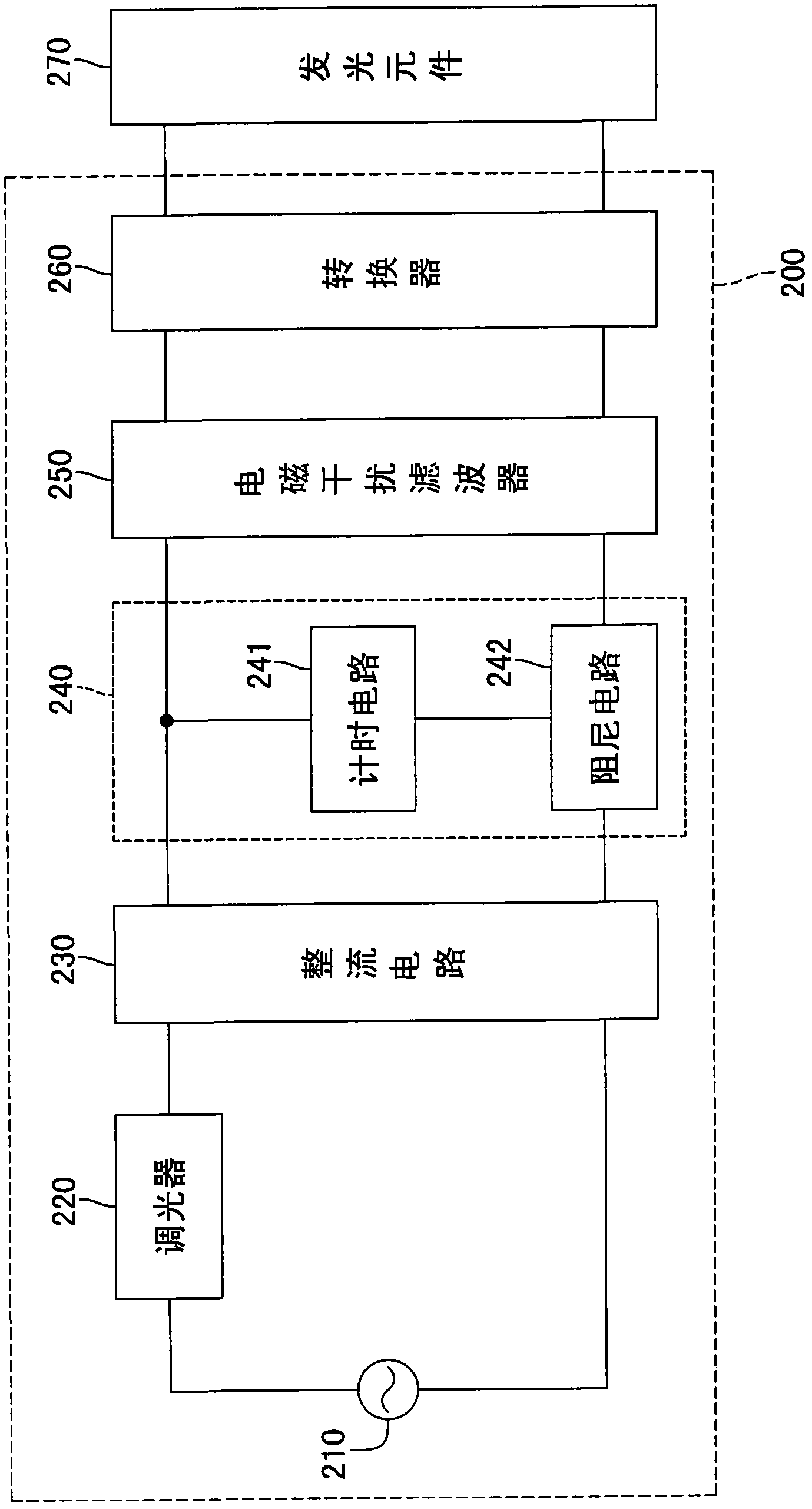
[0042] Please refer to figure 2 , is a system block diagram of a driving circuit according to an embodiment of the present invention. The driving circuit 200 of this embodiment is used to drive a light-emitting element 270, which includes an AC power supply 210, a dimmer 220, a rectifier circuit 230, a dynamic damping module 240, an electromagnetic interference filter 250 and a converter 260.

[0043] The AC power supply 210 supplies AC power to the dimmer 220 , and the dimmer 220 can adjust the power supplied to the light-emitting element 270 according to user requirements, so as to adjust the brightness or chroma of the light-emitting element 270 . In th...


PUM


Abstract

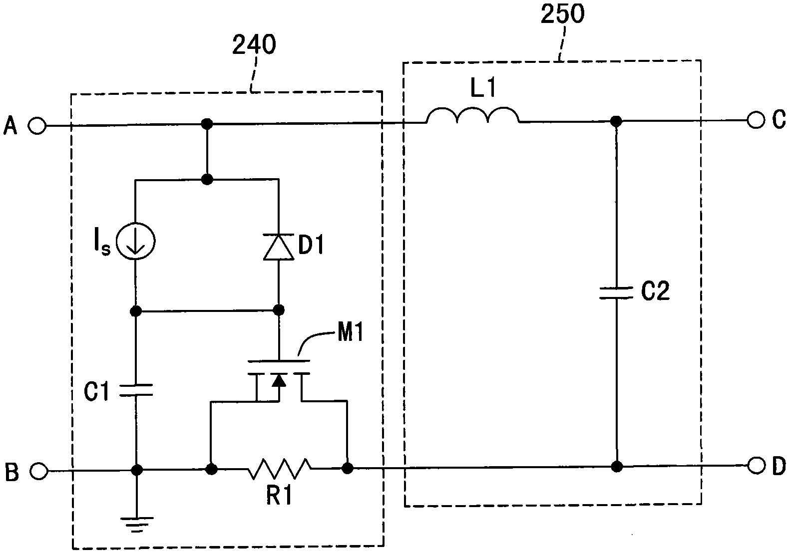
A dynamic damper (240) in a lighting driving circuit (200) for limiting an inrush current includes a damper circuit (242) and a timing circuit (241) comprising capacitor (1). The damper circuit is connected to the timing circuit. When an input voltage is provided to the dynamic damper, the capacitor begins to be charged and the capacitance-voltage of the capacitor rises. The damper circuit enters to a first working state and generates a dynamic damper resistor value. When the capacitance-voltage of the capacitor is greater than a first threshold voltage, the damper circuit enters to a second working state and the dynamic damper resistor value begins to decrease. When the capacitance-voltage of the capacitor is greater than a second threshold voltage, the damper circuit enters to a short-circuit state, and the dynamic damper resistor value decreases to zero to facilitate the normal work of the power source converter.

Description

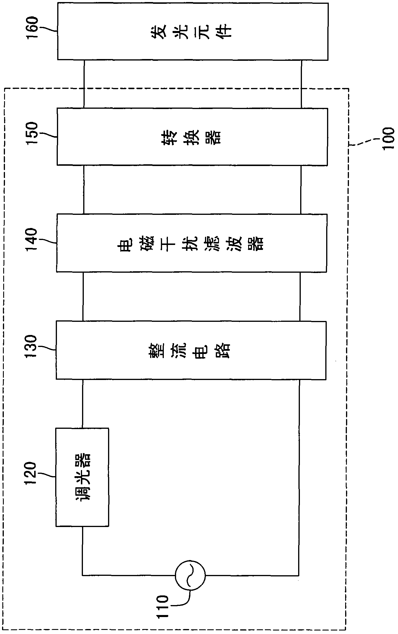
technical field [0001] The invention relates to a dynamic damping module, in particular to a dynamic damping module for limiting inrush current and a driving circuit for its application. Background technique [0002] Currently, the driving circuit used to drive the light-emitting elements generally uses a dimmer to adjust the brightness of the light-emitting elements. Generally speaking, a dimmer can be a triode for alternating current (TRIAC) or an SCR (silicon controlled rectifier), which can adjust the current, voltage or phase of the input AC power to achieve The purpose of adjusting the brightness of light-emitting elements. [0003] Please refer to figure 1 As shown, it is a system block diagram of a driving circuit in the prior art. The driving circuit 100 includes an AC power source 110 , a dimmer 120 , a rectifying circuit 130 , an EMI filter 140 and a converter 150 for supplying driving current to the light emitting element 160 . However, although the dimmer 12...

Claims


Application Information

Patent Timeline
Patent Type & Authority Applications(China)
IPC IPC(8): H02H9/02H05B37/02H05B44/00
CPCH05B33/0884H02H9/001H05B39/02H02M7/062H05B45/36H02M1/36H05B45/37H05B45/10H05B47/25Y02B20/30Y02B20/40
Inventor 张隆国刘兴富颜立维陈俊吉
Owner MACROBLOCK INC
Learn More