
Low current earth fault location method based on transient state current waveform comparison

A low-current grounding and fault location technology, applied in the fault location and other directions, can solve the problems of high hardware cost, reduced detection sensitivity and reliability, and inability to detect transient grounding faults.

Active Publication Date: 2013-07-24
SHANDONG UNIV OF TECH +1
View PDF4 Cites 48 Cited by
  • Summary
  • Abstract
  • Description
  • Claims
  • Application Information

AI Technical Summary

Problems solved by technology

This method has been applied to a certain extent, but has the following disadvantages: when the grounding resistance is large, the distributed capacitance on the line will shunt the injected signal, reducing the detection sensitivity and reliability; a dedicated high-power signal generator needs to be designed, and the hardware cost is high ; and cannot detect momentary ground faults
Therefore, the location of the fault point cannot be judged simply based on the similarity, and new methods need to be further studied to improve the adaptability of fault location

Method used


Image

  • Low current earth fault location method based on transient state current waveform comparison
  • Low current earth fault location method based on transient state current waveform comparison
  • Low current earth fault location method based on transient state current waveform comparison

Examples


Embodiment Construction

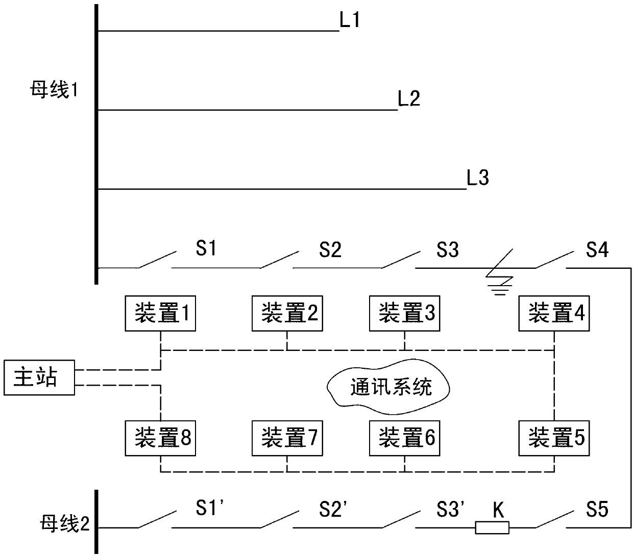
[0033] Figure 1~3 It is the best embodiment of the present invention, below in conjunction with attached Figure 1~3 The present invention is described further:

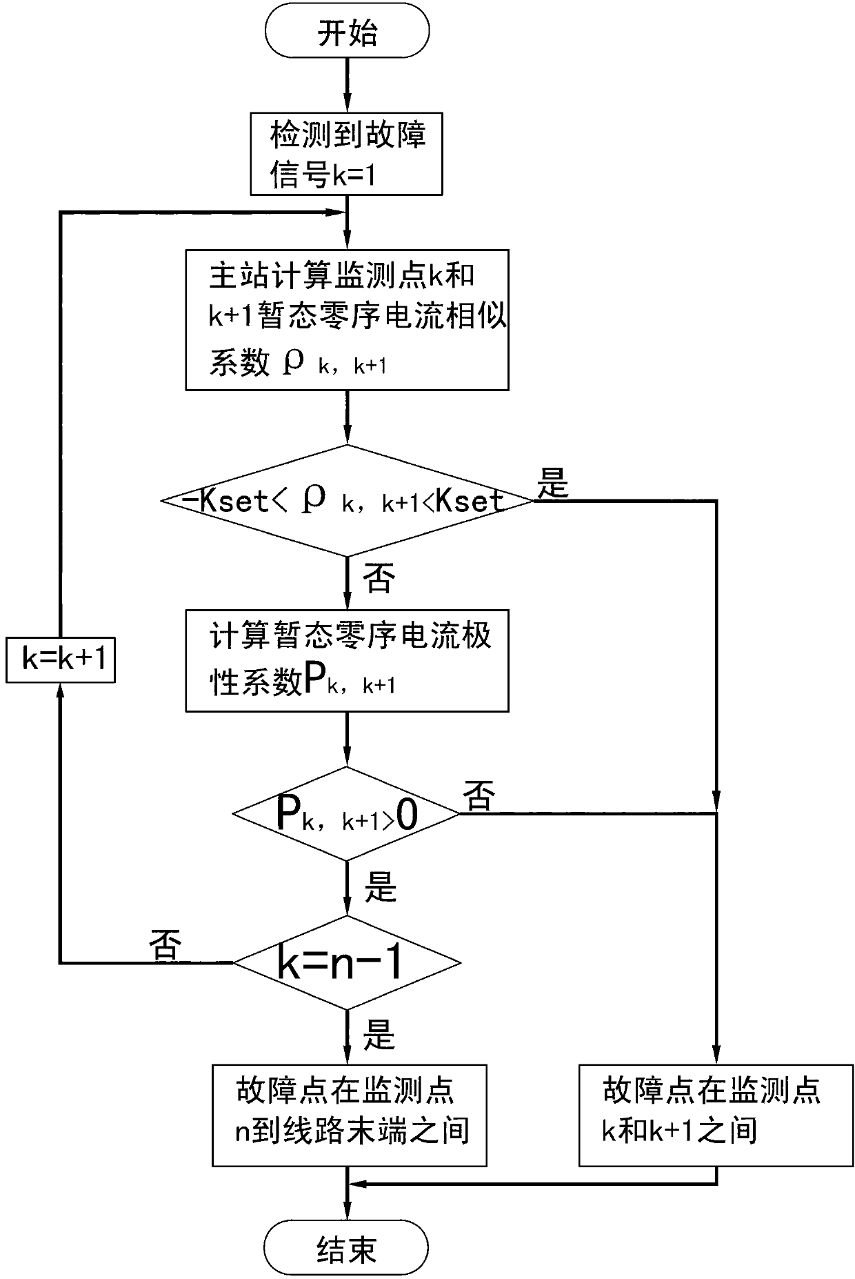
[0034] For small current grounding faults, due to the influence of the arc suppressing coil, weak fault current, and arc instability, the protection method based on the steady-state value is not ideal, and the amplitude of the transient signal is several times to several times larger than the steady-state value. Ten times, it can guarantee the protection sensitivity and reliability, and the transient protection is not affected by the arc suppression coil. The present invention comprehensively utilizes the positioning method of transient current similarity and polarity comparison. After a small current grounding fault occurs, firstly, the similarity coefficients of the transient zero-sequence currents of each adjacent detection point are compared sequentially from the detection points at the exit of the busbar. When...


PUM


Abstract

The invention discloses a low current earth fault location method based on transient state current waveform comparison and belongs to the filed of relay protection in an electric power system. A plurality of detection points arranged in an electric power circuit are utilized to upload fault zero sequence current data, and a master station receives and processes the data, and then conducts fault location judging. The location method is characterized by utilizing transient state zero sequence current similarity or / and polarity relationship to confirm a fault sector where fault points are located. The location method comprehensively utilizes the transient state zero sequence current similarity and the polarity relationship to conduct judging on the fault points, meanwhile is not influenced by unstable electric arc, can still precisely conduct location when the transient state zero sequence current similarity of the detection points on two sides of each fault point is high, and meanwhile has the advantage of being wide in application range.

Description

technical field [0001] The invention relates to a small current grounding fault location method based on comparison of transient current waveforms, which belongs to the field of electric system relay protection. In particular, the invention relates to a transient location method for a single-phase grounding fault in a small current grounding system. Background technique [0002] The small current ground fault location is based on the special fault indicator installed along the line or the distribution network automation (DA) system terminal, using the voltage and current information generated by the fault or the current information attached by other equipment to manually or automatically determine where the fault is located The segment between two pointers or terminals. [0003] From the perspective of technology itself, fault location can also be realized by using the amplitude and flow direction (polarity) relationship of power frequency zero-sequence current for unground...

Claims


Application Information

Patent Timeline
Patent Type & Authority Applications(China)
IPC IPC(8): G01R31/08
Inventor 徐丙垠薛永端王敬华
Owner SHANDONG UNIV OF TECH
Learn More