Spiral LED (light emitting diode) lamp cup
An LED lamp cup and spiral technology, which is applied in the field of electronics, can solve the problems that lamp cups cannot be mixed, and the heat dissipation effect of LED lamps is not ideal, so as to achieve the effect of facilitating heat dissipation.
Inactive Publication Date: 2013-07-17
JIANGSU JINGZHENG ELECTRONICS
View PDF4 Cites 0 Cited by
- Summary
- Abstract
- Description
- Claims
- Application Information
AI Technical Summary
Problems solved by technology
However, due to the difference in nature between LED lamps and incandescent lamps, the lamp cups of the two cannot be mixed; in addition, the heat dissipation effect of LED lamps is not ideal.
Method used
View moreImage
Smart ImageViewing Examples
Examples
Embodiment Construction
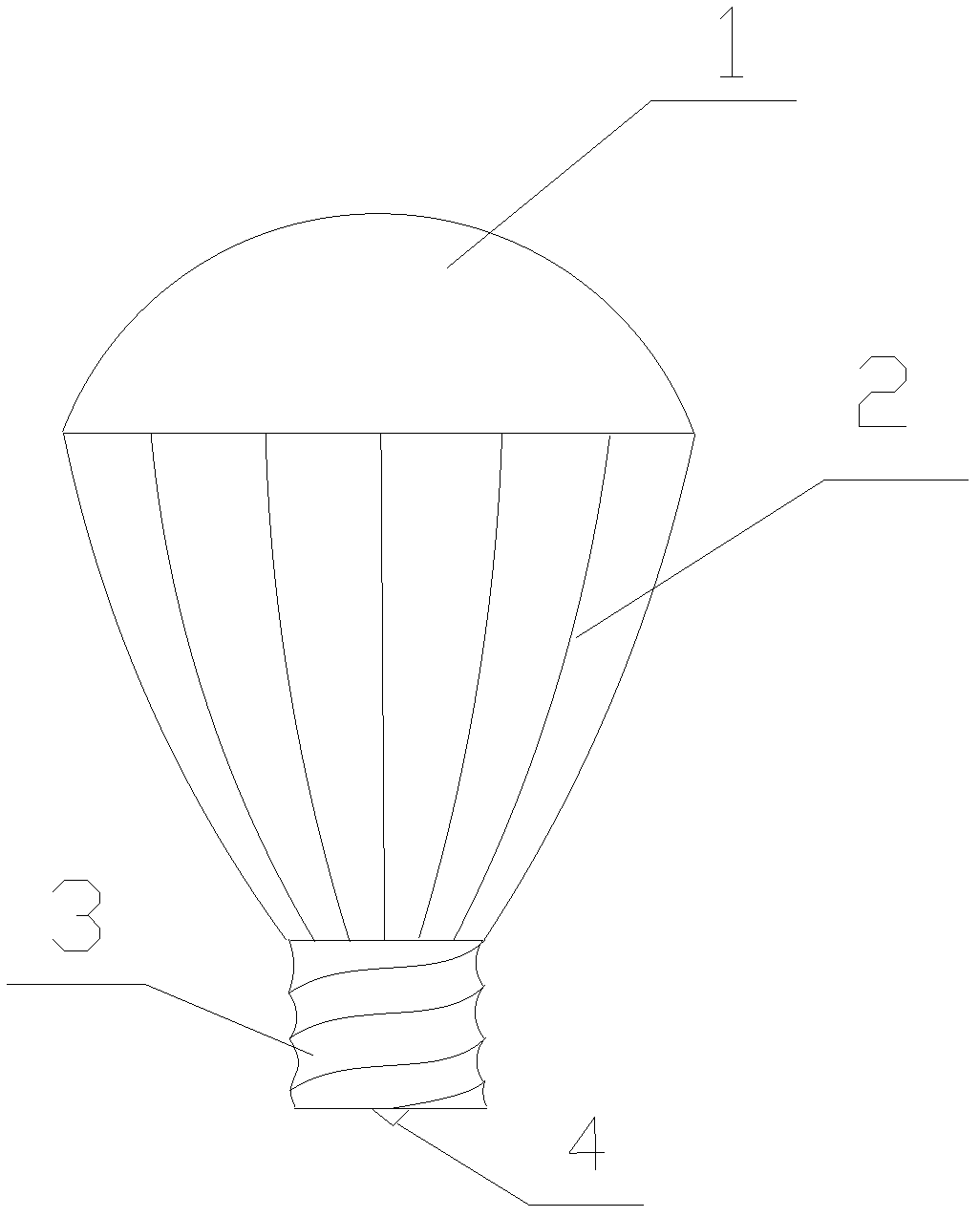
[0009] As shown in the figure, a spiral LED lamp cup disclosed by the present invention includes a lampshade 1, an aluminum strip heat sink 2, a driver 3 and electrode terminals 4, the lampshade 1 is connected to the top of the strip heat sink 2, The bottom of the bar-shaped cooling frame 2 is connected with a screw driver 3; the bottom of the driver 3 is provided with an electrode terminal 4.
Login to View More PUM
 Abstract
The invention discloses a spiral LED (light emitting diode) lamp cup, which comprises a lamp cover, a strip-shaped heat radiating frame, a driver and an electrode terminal, wherein the lamp cover is connected with the top of the strip-shaped heat radiating frame, the bottom of the strip-shaped heat radiating frame is connected with the driver, and the electrode terminal is arranged on the bottom of the driver. The spiral LED lamp cup is simple in structure and scientific in design, mixed use of lamp cups of an LED lamp and a filament lamp can be realized, by the adoption of the spiral driver, a stress surface of the LED lamp is enlarged, and more stress can be borne; and meanwhile by the adoption of the aluminium strip-shaped heat radiating frame, the radiation of heat inside a lamp is facilitated.
Description
technical field [0001] The invention belongs to the field of electronics, and in particular relates to an LED lamp cup. Background technique [0002] Compared with ordinary incandescent lamps, LED lamps have great advantages in energy saving and environmental protection, and have been widely used at present. However, due to the difference in nature between LED lamps and incandescent lamps, the lamp cups of the two cannot be mixed; in addition, the heat dissipation effect of LED lamps is not ideal. Contents of the invention [0003] Purpose of the invention: The purpose of the present invention is to provide a spiral LED lamp cup for the deficiencies of the prior art. [0004] Technical solution: In order to achieve the above purpose, the present invention is specifically realized as follows: a spiral LED lamp cup, including a lampshade, a strip-shaped cooling frame, a driver and electrode terminals, the lampshade is connected to the top of the strip-shaped cooling frame, ...
Claims
Login to View More Application Information
Patent Timeline
 Patent Type & Authority Applications(China)
IPC IPC(8): F21V29/00F21V23/06F21Y101/02F21V29/50F21V29/89F21Y115/10
Inventor 汪治兴
Owner JIANGSU JINGZHENG ELECTRONICS
- R&D Engineer
- R&D Manager
- IP Professional
- Industry Leading Data Capabilities
- Powerful AI technology
- Patent DNA Extraction
Learn More Browse by: Latest US Patents, China's latest patents, Technical Efficacy Thesaurus, Application Domain, Technology Topic, Popular Technical Reports.
© 2024 PatSnap. All rights reserved.Legal|Privacy policy|Modern Slavery Act Transparency Statement|Sitemap|About US| Contact US: help@patsnap.com


