High-rigidity low-deformation movable template

A technology of moving formwork and low deformation, applied in the field of high rigidity and low deformation moving formwork, can solve the problems of polluted products, increase the weight of moving formwork, reduce the precision of moving formwork, etc., and achieve the effect of eliminating pollution, low stress distribution and long service life.

Inactive Publication Date: 2013-07-17
BORCH MACHINERY
View PDF0 Cites 2 Cited by
  • Summary
  • Abstract
  • Description
  • Claims
  • Application Information

AI Technical Summary

Problems solved by technology

[0002] The movable platen in the clamping part of the traditional machine-hinged injection molding machine is guided by the tie rod when the mold is moved at high speed. The friction between the pull rod and the guide hole of the movable platen requires lubricating oil, which will cause the lubricating oil to contaminate the product; For the mould, which is transmitted to the mold surface, the hinge ear structure of the traditional movable template is set on the upper and lower sides of the movable template. When the mold area is relatively small, the clamping force will cause large bending deformation and bending stress on the code mold surface of the movable template. The current solution to this problem is to increase the thickness of the mold surface of the moving template, but the large increase in weight will lead to an increase in material costs and the increase in the weight of the moving template will lead to inflexibility of mold shifting and reduce the accuracy of mold shifting

Method used


Image

  • High-rigidity low-deformation movable template
  • High-rigidity low-deformation movable template

Examples


Embodiment Construction

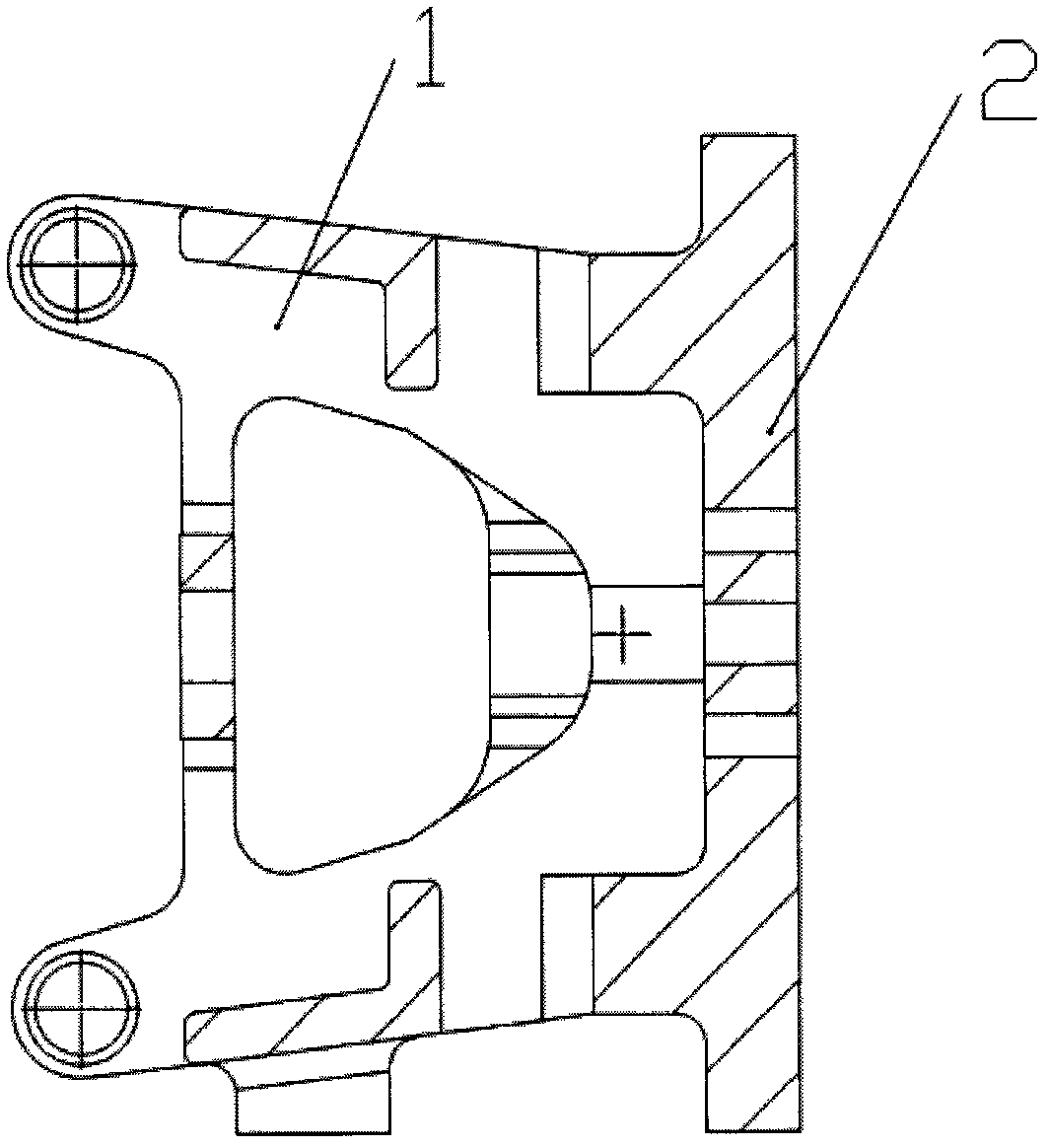
[0012] Such as figure 1 , figure 2 As shown, a high-rigidity and low-deformation movable formwork, which includes an A-shaped hinged ear frame (1), a dynamic formwork code mold surface (2), a central boss (3), an arc groove (4), and a small step surface (5), the A-shaped top of the A-shaped hinged ear frame (1) is provided with a moving template code mold surface (2), and the center positions of the left and right sides of the movable template code mold surface (2) are provided with a center The boss (3) can be equipped with a linear guide rail support and a linear guide rail. The four corners of the moving template code mold surface (2) are provided with arc grooves (4) to avoid pull bars. The movable template code mold surface ( 2) A tiny step surface (5) is set to counteract the slight deformation of the code mold surface (2) of the moving template.


PUM


Abstract

The invention relates to a high-rigidity low-deformation movable template. According to the movable template, a linear guide rail support is arranged by using central boss position minimum deformation areas on left and right sides, and a linear guide rail is then arranged. The guidance of the linear guide rail is used for replacing the guidance of four draw bar holes, such that the movable template does not contact the draw bar, and the movable template is prevented from lubricating oil pollution. According to the movable template, with an A-shaped hinge ear rack structure, clamping force is transmitted from hinge ear to the area close to the center of a movable template arrangement surface, such that movable template arrangement surface bending deformation and bending stress are reduced. Small sizes are respectively milled off on the upper and lower sides of the movable template arrangement surface from the centers to the outer sides, such that tiny stepped surfaces are formed, and movable template deformation is further offset. Therefore, when the mold is under clamping force, the influence caused by movable template deformation is minimized.

Description

Technical field [0001] The invention relates to a high-rigidity and low-deformation movable template in the clamping part of a machine-hinged injection molding machine. Background technique [0002] The movable platen in the clamping part of the traditional machine-hinged injection molding machine is guided by the tie rod when the mold is moved at high speed. The friction between the pull rod and the guide hole of the movable platen requires lubricating oil, which will cause the lubricating oil to contaminate the product; For the mould, which is transmitted to the mold surface, the hinge ear structure of the traditional movable template is set on the upper and lower sides of the movable template. When the mold area is relatively small, the clamping force will cause large bending deformation and bending stress on the code mold surface of the movable template. The current solution to this problem is to increase the thickness of the mold surface of the moving template, but the ...

Claims


Application Information

Patent Timeline
IPC IPC(8): B29C45/64
Inventor 叶廷璧罗婕
Owner BORCH MACHINERY
Why Eureka
Try Eureka