
A ladder wave generating circuit

A technology for generating circuits and ladder waves, which is applied in the direction of pulse generation, electrical components, pulse technology, etc., can solve the problems of reducing accuracy and the influence of ladder wave distortion, and achieve the effect of improving accuracy and avoiding nonlinear distortion

Active Publication Date: 2016-02-10
BEIJING SDL TECH
View PDF4 Cites 0 Cited by
  • Summary
  • Abstract
  • Description
  • Claims
  • Application Information

AI Technical Summary

Problems solved by technology

It can be seen that the pump-type ladder wave generating circuit uses diodes D1 and D2. Since the diodes are easily affected by the ambient temperature, the use of diodes will inevitably bring about certain nonlinear distortion, which will have a negative impact on the generated ladder wave. Distortion effects, reducing its accuracy

Method used


Image

  • A ladder wave generating circuit
  • A ladder wave generating circuit
  • A ladder wave generating circuit

Examples


Embodiment Construction

[0032] see figure 2 , the present invention provides a specific embodiment of a staircase wave generating circuit, the circuit includes a counting module 201 and a digital-to-analog conversion module 202 .

[0033] The counting module 201 is used to count a periodic pulse signal, and the t output terminals of the counting module 201 are respectively connected to the t input terminals of the digital-to-analog conversion module 202 . Among them, t is a natural number greater than 1.

[0034] Wherein, the n+i-th output terminal of the counting module 201 is connected to the m+i-th input terminal of the digital-to-analog conversion module 202, and n is the lowest bit in the output terminal connected to the digital-to-analog conversion module 202 in the counting module 201, m is the lowest bit in the input terminal connected to the counting module 201 in the digital-to-analog conversion module 202, and i is any self-heating number satisfying 0≤i≤t-1. That is to say, the t adjace...


PUM


Abstract

The invention provides a step wave generating circuit which comprises a counting module and a digit-to-analogue conversion module. The counting module is used for counting a periodic pulse signal, t output ends of the counting module are respectively connected with t input ends of the digit-to-analogue conversion module, wherein the (n+1)th output end of the counting module is connected with the (m+1)th input end of the digit-to-analogue conversion module, n is the lowest digit of the output ends of the counting module, the output ends of the counting module are connected with the digit-to-analogue conversion module, and m is the lowest digit of the input ends of the digit-to-analogue conversion module, and the input ends of the digit-to-analogue conversion module are connected with the counting module. Due to the fact that the counting module conducts counting on the periodic pulse signal, the digit-to-analogue conversion module converts a count value of the counting module into an ji signal to produce the step wave signal. Therefore, no diode is used in the step wave generating circuit, non-linear distortion produced by influence of temperature of the diode is avoided, and therefore precision of the produced step wave is improved.

Description

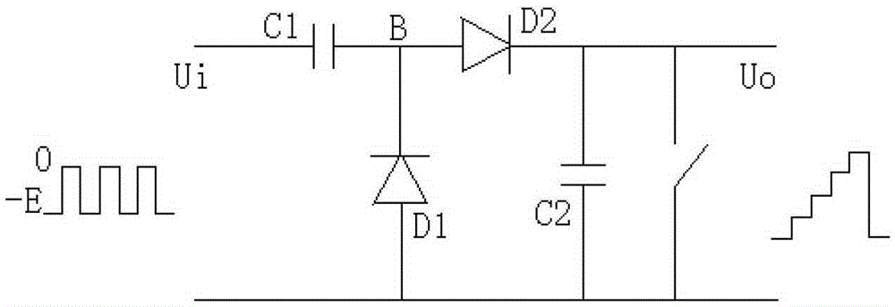
technical field [0001] The invention relates to the field of electronic circuits, in particular to a staircase wave generating circuit. Background technique [0002] Staircase wave is an analog signal commonly used in the field of electronic circuit design. figure 1 It is a pump-type ladder wave generating circuit, which is composed of diodes D1, D2 and capacitors C1 and C2. The input signal Ui is a periodic pulse signal with the highest value of 0 and the lowest value of -E. When the input signal drops from 0 to -E When the diode D1 is turned on, the diode D2 is turned off, and the input signal charges the capacitor C1. Since the equivalent resistance of the diode D1 is very small, the capacitor C1 is quickly charged to E. When the input signal rises from -E to 0, due to The voltage across the capacitor C1 cannot change abruptly, so the potential at point B is +E. At this time, D1 is turned off, D2 is turned on, and the capacitor C2 begins to charge. At this time, the capa...

Claims


Application Information

Patent Timeline
Patent Type & Authority Patents(China)
IPC IPC(8): H03K4/02
Inventor 梁学军
Owner BEIJING SDL TECH
Learn More