Decoupling method of air vehicle pneumatic strong coupling

A pneumatic coupling and aircraft technology, applied in the direction of instruments, non-electric variable control, position/direction control, etc., can solve problems such as poor decoupling effect

Inactive Publication Date: 2013-07-10
NORTHWESTERN POLYTECHNICAL UNIV
View PDF2 Cites 12 Cited by
  • Summary
  • Abstract
  • Description
  • Claims
  • Application Information

AI Technical Summary

Problems solved by technology

[0005] In order to overcome the shortcomings of poor decoupling effect of existing robust decoupling control met...

Method used


Image

  • Decoupling method of air vehicle pneumatic strong coupling
  • Decoupling method of air vehicle pneumatic strong coupling
  • Decoupling method of air vehicle pneumatic strong coupling

Examples


Embodiment Construction

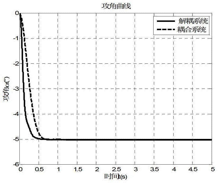
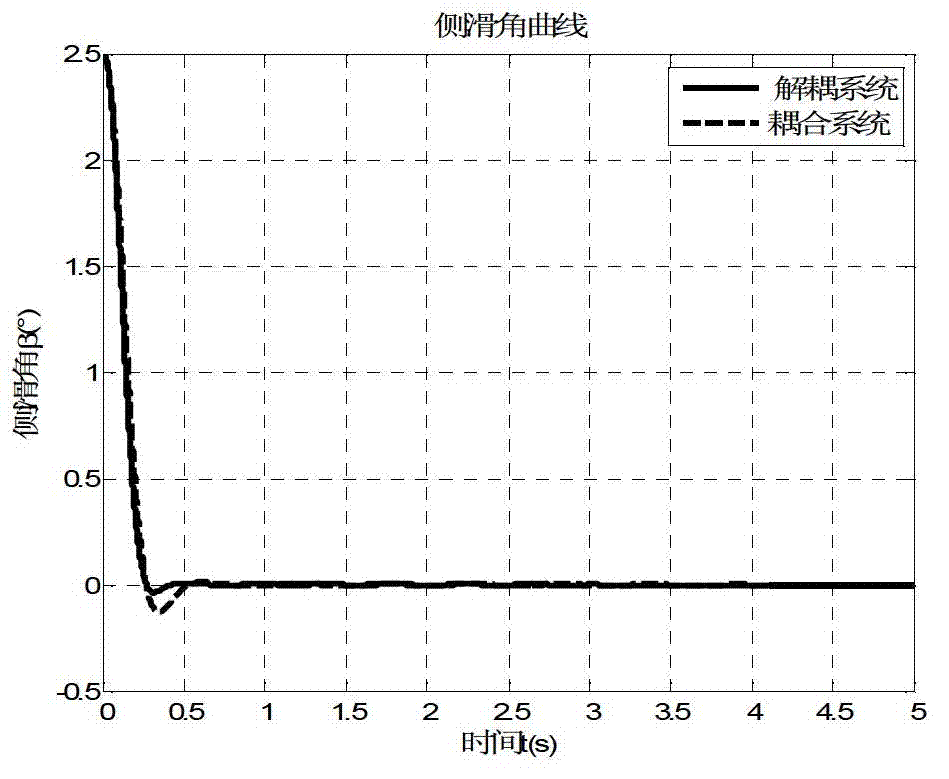
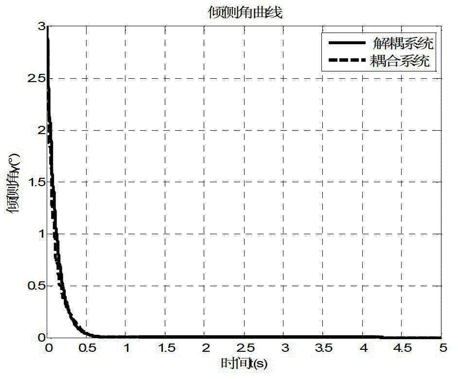
[0118] Reference Figure 1~3 . The specific steps of the aerodynamic strong coupling decoupling method of the aircraft of the present invention are as follows:

[0119] Step 1: The aerodynamic torque coupling model is established.

[0120] The aerodynamic coupling of the aircraft is embodied in that the parameters of the longitudinal motion not only affect the aerodynamic force and torque of the longitudinal motion, but also affect the aerodynamic force and the torque of the lateral motion. At the same time, the parameters of lateral motion not only affect the aerodynamic force and moment of lateral movement, but also affect the aerodynamic force and moment of longitudinal motion. The aerodynamic coupling model decoupling method of the present invention focuses on attitude decoupling, so the focus here is the characterization of the aerodynamic moment equation.

[0121] 1) Pitch channel.

[0122] The moment of the pitch channel is also called the longitudinal moment, and its functi...


PUM


Abstract

The invention discloses a decoupling method of air vehicle pneumatic strong coupling to solve the technical problem that an existing robust decoupling control method of a high ultrasonic air vehicle is poor in decoupling effect. The technical scheme is that the decoupling method comprises the steps of first establishing a pneumatic torque coupling model, then defining pneumatic coupling evaluation criteria, then defining pneumatic coupling characteristics, setting pneumatic coupling decoupling conditions, and completing decoupling of air vehicle pneumatic strong coupling. Due to the fact that all coupling factors are reasonably divided and classified in the method, equivalent effect of coupling factors of a same type is realized, and the definition for evaluating and analyzing the pneumatic coupling evaluation criteria-coupling degrees is introduced. According to the influences on air vehicle characterizes from different coupling degrees, coupling effects are divided into strong coupling and weak coupling, and decoupling methods-coupling ignoring and coupling equivalent conversion under pneumatic weak coupling and pneumatic strong coupling are refined, and therefore the decoupling effect of the air vehicle pneumatic strong coupling is improved.

Description

Technical field [0001] The invention relates to an aerodynamic decoupling method for an aircraft, in particular to an aerodynamic strong coupling decoupling method for an aircraft. Background technique [0002] Different from traditional aircraft, hypersonic aircraft has high flying speed and large airspace. There is a strong aerodynamic cross-coupling between the three channels. The aerodynamic layout methods such as plane symmetry and wing-body fusion make the aerodynamic coupling between channels more obvious. The aerodynamic forces of each lifting surface of the aircraft and the motion parameters of each channel are cross-linked and affected. The motion attitude, attitude angle and steering mechanism deflection angle of each channel not only affect the aerodynamic moment received by the aircraft in this channel, but also affect the aircraft in other channels. The magnitude of the aerodynamic torque also has a coupling effect, which brings great difficulties to the design of t...

Claims


Application Information

Patent Timeline
IPC IPC(8): G05D1/00
Inventor 周军林鹏朱多宾周敏耿克达
Owner NORTHWESTERN POLYTECHNICAL UNIV
Why Eureka
Try Eureka