
Screw type soil-taking and sample-cutting apparatus

A screw-type, sample-cutting technology, applied in the direction of sampling device, etc., can solve the problem that it is difficult to press the ring knife into the sample, and achieve the effect of improving efficiency and quality, and applying force uniformly

Inactive Publication Date: 2013-07-10
LANZHOU UNIVERSITY
View PDF9 Cites 24 Cited by
  • Summary
  • Abstract
  • Description
  • Claims
  • Application Information

AI Technical Summary

Problems solved by technology

In the traditional experiment, the ring knife is pressed down into the soil sample by manual direct pressing. However, if the soil is hard, it is difficult to manually press the ring knife into the sample.

Method used


Image

  • Screw type soil-taking and sample-cutting apparatus

Examples


Embodiment 1

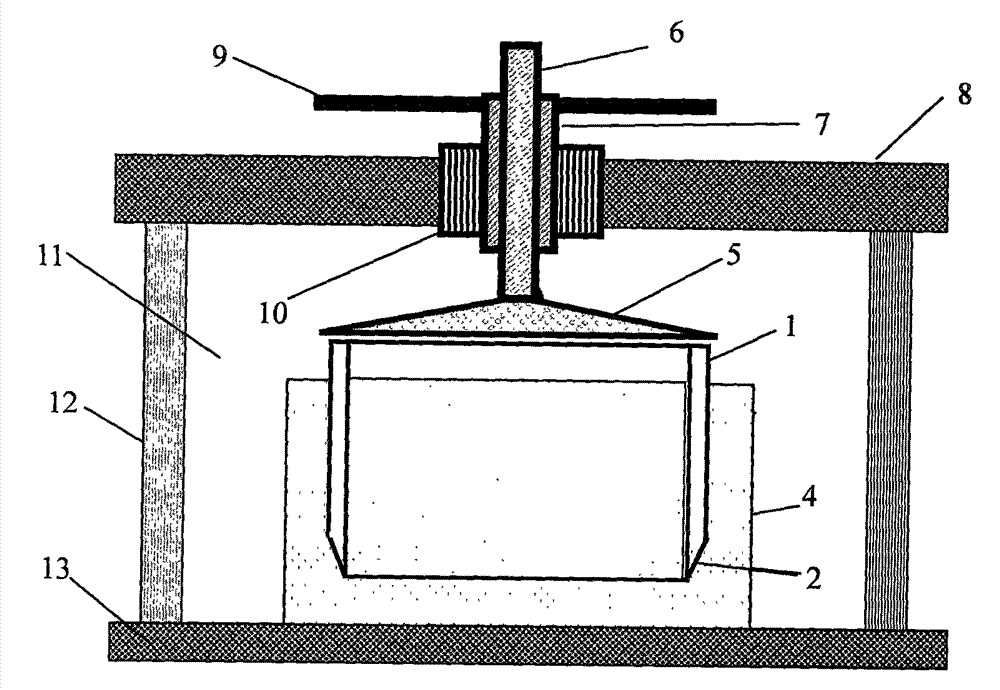
[0011] Design a screw type soil sample cutting device of the present invention, see figure 1 , design a sampling table that can be installed with a screw device, the sampling table includes: a metal circular base 13 with a diameter of 100 mm and a thickness of 10 mm, and four cylindrical support columns 12 with a diameter of 20 mm and a height of 100 mm are fixed evenly and vertically on the edge of the base 13, The upper end of the column 12 is connected with a ring knife seat top plate 8, which is the main force-bearing part when the screw rod of the present invention is propelled. 8 can be easily installed and removed from the support column 12, such as being fixed by buckles or magnets. The ring cutter seat top plate 8 is a metal round platform with a diameter of 100mm and a thickness of 18mm, which is made of rigid hard material and can be turned to bear larger pressure without deformation.

[0012] A bearing 10 with an outer diameter of 40mm, an inner diameter of 20mm, ...

Embodiment 2

[0014] The above-mentioned screw-type soil sampling and cutting device is further improved. On the basis of Embodiment 1, a groove is designed on the bottom plane of the pressure plate 5 at the contact of the pressure plate 5 and the ring knife 1, and the pressure plate 5 When applying pressure to the ring knife 1, the tail of the ring knife 1 can just enter the groove, preventing the pressure plate 5 from sliding relative to the ring knife 1 during the pressure application process. The groove here is circular, concentric with the plane of the cone bottom of the pressing plate 5, the inner diameter of the groove is 62mm, the width is 2mm, and the depth is 2mm.


PUM

PropertyMeasurementUnit
Diameteraaaaaaaaaa

Abstract

The invention relates to a screw type soil-taking and sample-cutting apparatus. A separable screw device is additionally arranged on a soil-taking cutting ring; the screw device comprises a cutting ring seat top board and a support column perpendicular to and fixedly connected with a pedestal, wherein the cutting ring seat top board is located at the upper part of the support column and is movably connected with the support column through a bolt, the central position of the cutting ring seat top board is provided with a bearing capable of sliding along the cutting ring seat top board, a movable bolt on the bearing is connected with a force applying rod, and the cutting ring is arranged below a force applying plate. During soil sampling, a soil sample is placed on the pedestal of the apparatus, then the blade of the cutting ring is downwardly put on the soil sample, the cutting ring seat top board is pulled upwardly to allow the force applying plate to be rightly placed on the top of the cutting ring, and then the cutting ring seat top board is forcibly pulled upwards to allow the force applying plate to uniformly exert forces on the cutting ring so as to enable the cutting ring to enter into the soil sample. According to the invention, the cutting ring is improved, so the cutting ring can be smoothly pressed into a hard soil sample for sampling by using ordinary manual pushing; and force application is uniform in the whole sampling process, and sampling efficiency and quality are improved.

Description

technical field [0001] The invention relates to the field of civil engineering sampling tools, in particular to a soil sampling and cutting device. Background technique [0002] The ring knife is a kind of test equipment used for soil engineering tests. It is mainly used to prepare soil samples for testing such as soil density and water content. A ring knife is essentially a rigid, open-ended cylindrical sleeve with a sharper edge at one end. In specific use, a relatively large soil sample is prepared first, and then the ring knife is placed on the soil sample, the cutting edge is in contact with the surface of the sample, and then pressed down firmly to make the ring knife enter the soil sample. In the process of forcefully moving the ring knife downward, the blade of the ring knife cuts into the surrounding soil samples. When the ring knife completely enters and penetrates the soil sample layer, the soil sample in the ring knife is taken out to make a complete sample. so...

Claims


Application Information

Patent Timeline
IPC IPC(8): G01N1/04
Inventor 赵忠虎
Owner LANZHOU UNIVERSITY
Learn More