Method of lifting steel box beam with steel lifting bands and hydraulic device

A technology of hydraulic devices and slings, which is applied to the erection/assembly of bridges, bridges, bridge construction, etc., which can solve the problems of high labor intensity, high cost of block assembly, poor stability, etc., and achieve simple, stable and reliable structure and complete construction Increased level, excellent effect of use

Active Publication Date: 2015-04-01
CHINA METALLURGICAL CONSTR ENG GRP
View PDF5 Cites 0 Cited by
  • Summary
  • Abstract
  • Description
  • Claims
  • Application Information

AI Technical Summary

Problems solved by technology

[0003] There are two main methods of hoisting and installation of the existing finished T-beams and box girders of various types: the first method is to use multiple hydraulic jacks with brackets to lift the beam, and the second method is to install a winch on the mast to realize lifting The finished beam has the following deficiencies in field use: 1. The labor intensity is high, requiring multiple hydraulic jacks with brackets to lift the beam, and there are many auxiliary steel piers; many workers are required for auxiliary lifting 2. Install a hoist on the mast to lift the finished beam, and the hoist installed with it has a large tonnage and poor stability, and the cost of the pulley block is extremely high; 3 , The self-weight of the whole machine is more than 5T, which belongs to the lifting special inspection exceeding the standard machinery, and its own installation and movement are both cumbersome and do not meet industry standards

Method used


Image

  • Method of lifting steel box beam with steel lifting bands and hydraulic device
  • Method of lifting steel box beam with steel lifting bands and hydraulic device

Examples


Embodiment Construction

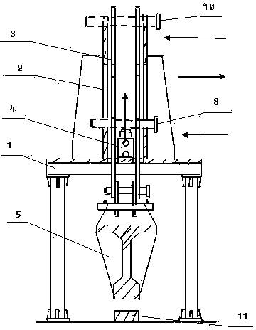
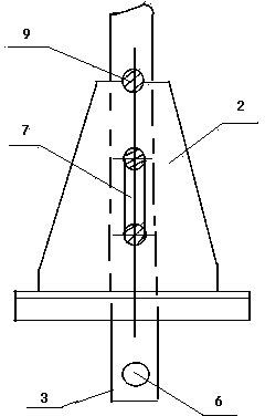
[0021] The present invention adopts steel sling and hydraulic device to lift the method for the prefabricated beam, and it is characterized in that:

[0022] 1. According to the size and weight of the finished beam, make steel slings. There are several pin holes arranged up and down on the steel slings; for the convenience of use, the pin holes on the steel slings are set equidistantly.

[0023] 2. Lift and connect the left and right two steel slings with the two ends of the finished beam; and install an electro-hydraulic jack as a power device for lifting the finished beam. When the ejector rod of the electro-hydraulic jack reciprocates, it can push the left and right The two steel slings reciprocate up and down; beside the left and right two steel slings, a support plate is respectively set up, and a strip-shaped slot hole is set on the support plate, and several pin holes correspond to the steel slings. holes; both the support plate and the electro-hydraulic jack are suppor...


PUM


Abstract

The invention discloses a method of lifting a pre-fabricated finished beam with steel lifting bands and a hydraulic device. The method includes that steel lifting bands with a plurality of pin holes which are vertically arranged and spaced equally are produced, strip slot holes and holes corresponding to the pin holes of the steel lifting bands are arranged on a supporting plate, steel pins are penetrated through the pin holes of the left and the right two steel lifting bands and the lower end of the strip slot holes, an electric hydraulic jack is started for jacking upwards to enable the left and the right two steel lifting bands to move upwards to drive one end of the finished beam to move upwards, a first movement of the pre-fabricated finished beam is completed when the steel pins move to the upper end of the strip slot holes, and force bearing pins are penetrated through through-holes formed by the pin holes of the steel lifting bands and the strip slot holes of the supporting plate to bear the weight of the finished beam. According to the method, a winch is replaced by the electric hydraulic jack and a pulley block is replaced by the steel lifting bands, so that the use cost of devices is reduced, the entire weight of a machine is reduced to obtain the lightness of the machine in operation and working, the structure is simple, stable and reliable, the installation is light and easy, the security is high, the productization can be completely obtained.

Description

technical field [0001] The invention relates to a method in the field of bridge construction, in particular to a method for hoisting and installing prefabricated steel box girders (finished T-beams and box girders of various types) using steel slings and hydraulic devices to lift finished beams. Background technique [0002] In the field of bridge construction, with the development of construction technology, more and more prefabricated steel box girders (finished T-beams and various types of box girders) are used to erect viaducts. Lifting and installation of prefabricated T-beams and various box girders to meet the requirements of construction technology. [0003] There are two main methods of hoisting and installation of the existing finished T-beams and box girders of various types: the first method is to use multiple hydraulic jacks with brackets to lift the beam, and the second method is to install a winch on the mast to realize lifting The finished beam has the fo...

Claims


Application Information

Patent Timeline
Patent Type & Authority Patents(China)
IPC IPC(8): E01D21/00
Inventor 陈国民谭治强
Owner CHINA METALLURGICAL CONSTR ENG GRP
Why Eureka
Try Eureka