
Thermal printer and control method of thermal printer

A technology of a thermal printer and a control method, which is applied to printing devices, printing, etc., can solve problems such as complex structures of thermal printers, and achieve the effect of solving complex structures and simplifying the structure of thermal printers

Active Publication Date: 2013-07-10
SHANDONG NEW BEIYANG INFORMATION TECH CO LTD
View PDF11 Cites 11 Cited by
  • Summary
  • Abstract
  • Description
  • Claims
  • Application Information

AI Technical Summary

Problems solved by technology

[0005] The main purpose of the present invention is to provide a thermal printer and a control method of the thermal printer, so as to solve the problem that the structure of the thermal printer with scanning function is relatively complicated

Method used


Image

  • Thermal printer and control method of thermal printer
  • Thermal printer and control method of thermal printer
  • Thermal printer and control method of thermal printer

Examples


Embodiment Construction

[0025] It should be noted that, in the case of no conflict, the embodiments in the present application and the features in the embodiments can be combined with each other. The present invention will be described in detail below with reference to the accompanying drawings and examples.

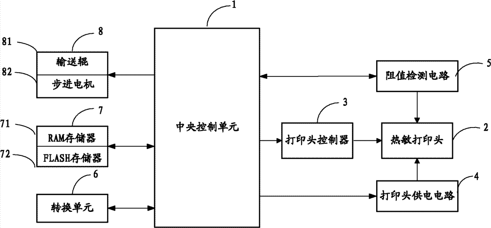
[0026] figure 2 is a schematic diagram of a thermal printer according to an embodiment of the present invention. As shown in the figure, the thermal printer includes a central control unit 1 , a thermal print head 2 , a print head controller 3 , a print head power supply circuit 4 , a detection circuit 5 , a conversion unit 6 , a storage unit 7 and a transport mechanism 8 .

[0027] The central control unit 1 can be a microprocessor, which is used to control each module to perform work.

[0028] The thermal head 2 is used to perform printing or scanning operations.

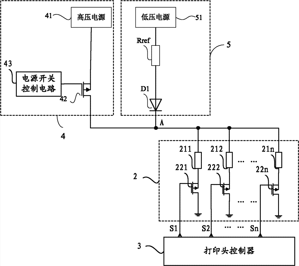
[0029] The print head controller 3 is connected with the thermal print head 2, and the signal output by the print head contro...


PUM


Abstract

The invention discloses a thermal printer and a control method of the thermal printer. Then thermal printer comprises a thermal printing head. In the control method, the thermal printing head is controlled to scan original manuscripts to obtain image data of the original manuscripts. The thermal printing head is not only used for carrying out printing work, but also scanning work can be carried out, and the problem that the thermal printer with a scanning function is complex in structure is solved.

Description

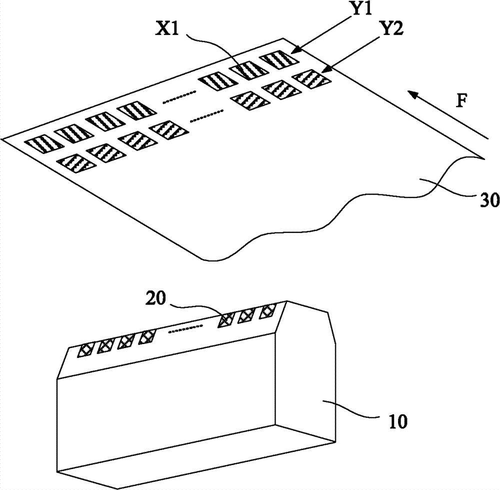
technical field [0001] The invention relates to the printing field, in particular to a thermal printer and a control method for the thermal printer. Background technique [0002] figure 1 It is a schematic diagram of the corresponding relationship between the heating element and the medium of the traditional thermal print head. As shown in the figure, the thermal print head includes a plurality of heating elements 20, and these heating elements 20 are equidistantly arranged in a row. The number of heating elements 20 is set according to the lateral resolution of the printing head. When the horizontal resolution of the print head is 203 dots / inch, the heating elements 20 are arranged at a density of 203 dots per inch. The heating element 20 is usually a thermistor. When the heating element 20 is energized, the thermistor generates heat to cause chemical changes in the heat-sensitive layer on the surface of the printing paper, thereby developing color. Since each heating e...

Claims


Application Information

Patent Timeline
Patent Type & Authority Applications(China)
IPC IPC(8): B41J2/32B41J29/393
CPCB41J2/32B41J2/35
Inventor 董述恂丛强滋姜天信王春涛王永华韩智华
Owner SHANDONG NEW BEIYANG INFORMATION TECH CO LTD
Learn More