
Dry distillation cigarette

A cigarette, dry distillation technology, applied in the direction of tobacco, cigar manufacturing, application, etc., can solve the problems of difficult ignition, harm to health, inhalation, etc., and achieve the effects of low production cost, easy rolling and processing, and convenient manufacturing.

Active Publication Date: 2013-07-10
HUBEI CHINA TOBACCO IND +1
View PDF4 Cites 21 Cited by
  • Summary
  • Abstract
  • Description
  • Claims
  • Application Information

AI Technical Summary

Problems solved by technology

[0004] The cigarette carbon heat source of R.J. Reynolds Tobacco Company adopts the method of wrapping carbon rods with glass fibers. However, the carbon rods are formed by extrusion, and the inside is dense. In order to form hot air flow, the outer layer needs to be wrapped with breathable glass fibers. Some studies believe that, Even if such particles can be retained by the filter material, they will inevitably be adsorbed on the filter during packaging and other processes, resulting in inhalation and endangering health. At the same time, dense carbon rods are also more difficult to ignite than slender carbon filamentous materials.

Method used


Image

  • Dry distillation cigarette
  • Dry distillation cigarette
  • Dry distillation cigarette

Examples


Embodiment 1

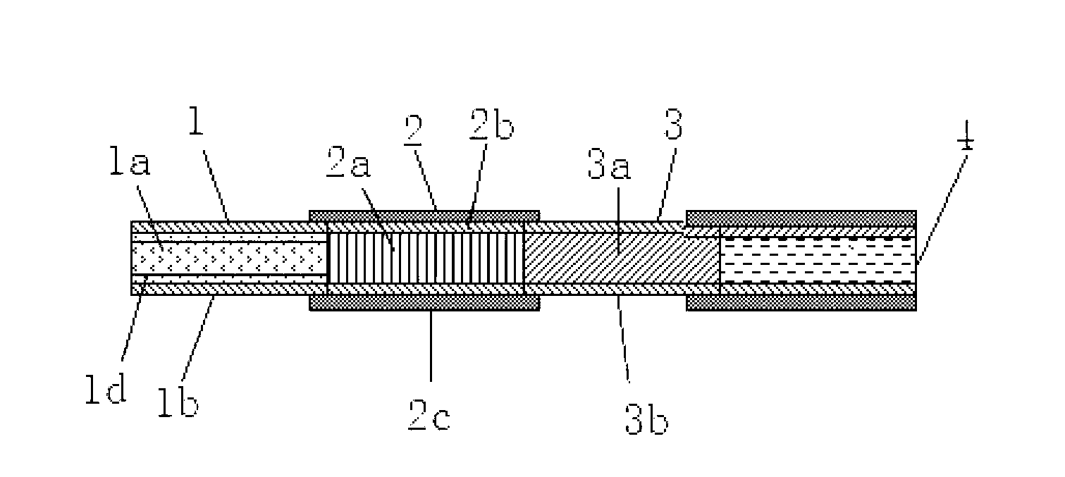
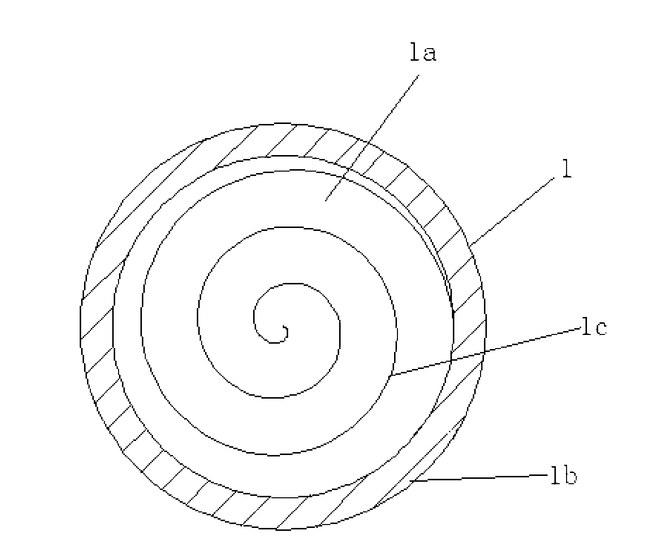
[0025] like figure 1 and figure 2 As shown, a dry distillation type cigarette is composed of a heat source section 1, a dry distillation section 2, a filling section 3 and a stick section 4, and the heat source section 1, the dry distillation section 2, the filling section 3 and the stick section 4 are connected in sequence. The heat source section 1 includes a carbonaceous heat source 1a and a cigarette paper 1b wrapped in the outer layer of the carbonaceous heat source 1a, and the retort section 2 is composed of retort shredded tobacco 2a, a heat-conducting and insulating layer 2b, and a flame-retardant wrapping layer 2c from the inside to the outside. The filling section 3 is composed of a tobacco product 3a and a cigarette paper 3b for wrapping the tobacco product 3a.

[0026] The inside of the carbonaceous heat source 1a is provided with a pore 1c penetrating in the axial direction. The carbonaceous heat source 1a is a multi-layer structure rolled from a sheet-like carb...

Embodiment 2

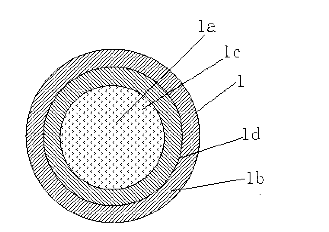
[0028] like figure 1 and image 3 As shown, a dry distillation type cigarette is composed of a heat source section 1, a dry distillation section 2, a filling section 3 and a stick section 4, and the heat source section 1, the dry distillation section 2, the filling section 3 and the stick section 4 are connected in sequence. The heat source section 1 includes a carbonaceous heat source 1a and a cigarette paper 1b wrapped in the outer layer of the carbonaceous heat source 1a, and the retort section 2 is composed of retort shredded tobacco 2a, a heat-conducting and insulating layer 2b, and a flame-retardant wrapping layer 2c from the inside to the outside. The filling section 3 is composed of a tobacco product 3a and a cigarette paper 3b for wrapping the tobacco product 3a.

[0029] The interior of the carbonaceous heat source 1a is provided with pores 1c penetrating in the axial direction. The carbonaceous heat source 1a is a porous structure made of filamentous carbonaceous m...


PUM

PropertyMeasurementUnit
Draw resistanceaaaaaaaaaa

Abstract

The invention discloses a dry distillation cigarette, comprising a heat source section, a dry distillation section, a filling section and a chewing bar section, wherein the heat source section, the dry distillation section, the filling section and the chewing bar section are orderly connected; the heat source section comprises a carbon heat source and cigarette paper coated at the outer layer of the carbon heat source; and a hole penetrating along the axial direction is formed inside the carbon heat source. The carbon heat source disclosed by the invention is not coated by a glass fiber. Thus, the damage generated when the glass fiber is inhaled by a human body is reduced; and the heat source section has a good air flow channel, so that the flammability of the carbon heat source and the atomizing effect of a pipe tobacco are better.

Description

[0001] The invention belongs to the field of cigarettes, and in particular relates to dry distillation cigarettes. Background technique [0002] Studies have shown that nicotine and most tobacco flavor components can be transferred to smoke at lower temperatures (300-500°C). If the temperature of the cigarette is lowered to below 600°C (the ignition point of tobacco is about 700°C), various harmful components of the smoke can be greatly reduced, while the aroma components are relatively less affected. Therefore, a kind of cigarette that utilizes carbonaceous heat source to carry out dry distillation tobacco component is invented. [0003] Retort cigarettes are mainly composed of four parts, namely heat source section, dry distillation section, filling section and stick section. The heat source section is based on carbon rods, and the outer layer is wrapped with a breathable layer and ordinary cigarette paper in turn; the dry distillation section is divided into three layers f...

Claims


Application Information

Patent Timeline
IPC IPC(8): A24D1/00
Inventor 罗诚浩陈义坤魏敏宋旭艳潘曦
Owner HUBEI CHINA TOBACCO IND
Learn More