Current/voltage conversion circuit with filtering and amplification functions

A technology of voltage conversion circuit and amplification function, which is applied in the direction of logic circuit connection/interface layout, etc., which can solve the problems of long response time of current-to-voltage circuit, large input current signal amplitude, and small voltage signal amplitude, etc., so as to facilitate follow-up processing, wide dynamic range, and amplitude enhancement

Inactive Publication Date: 2013-07-03
KUSN LANLING TECH
View PDF0 Cites 4 Cited by
  • Summary
  • Abstract
  • Description
  • Claims
  • Application Information

AI Technical Summary

Problems solved by technology

[0002] In many existing experiments, the current signal is converted into a voltage signal through electronic components. Although these conversion circuits can obtain a voltage signal, they often require a large input current signal amplitude and a small dynamic range, or the obtained voltage signal carries a relatively large noise, or the amplitude of the voltage signal is relatively small, or the response time of the current-to-voltage circuit is long
The resulting voltage signal will have a certain negative impact on the next step of the experiment
Therefore, there is no current / voltage conversion circuit that can detect a weak current signal less than 1nA and convert it into a voltage signal within a dozen microseconds. The voltage signal is passed through an active low After the noise is reduced by the filter circuit, the voltage signal is amplified

Method used


Image

  • Current/voltage conversion circuit with filtering and amplification functions
  • Current/voltage conversion circuit with filtering and amplification functions
  • Current/voltage conversion circuit with filtering and amplification functions

Examples


Embodiment 1

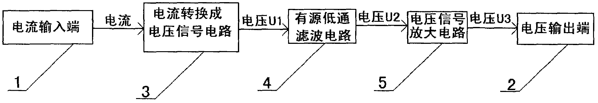
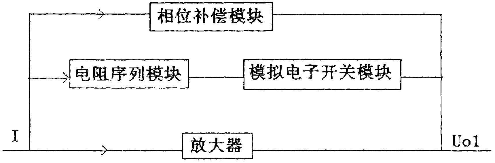
[0016] Example 1, figure 1 Shows the module schematic diagram of the current / voltage conversion circuit with filtering and amplification functions of the present invention, figure 2 It shows a schematic diagram of the circuit structure in which the current is converted to the initial voltage in a current / voltage conversion circuit with filtering and amplification functions of the present invention;

[0017] Such as figure 1 Shown: a current / voltage conversion circuit with filtering and amplification functions, including: current input terminal 1, voltage output terminal 2, characterized in that: current / voltage conversion signal circuit 3, filter circuit 4, voltage signal amplification circuit 5. The connection relationship between each circuit is: the current input terminal 1 is respectively connected to the resistor 6' in the current detection resistor sequence 6, one switch 7' in the multi-channel selection switch 7 is in the closed state, and the other switches 7' are in...

Embodiment 2

[0022] Example 2, figure 1 Shows the module schematic diagram of the current / voltage conversion circuit with filtering and amplification functions of the present invention, figure 2 It shows a schematic diagram of the circuit structure in which the current is converted to the initial voltage in a current / voltage conversion circuit with filtering and amplification functions of the present invention;

[0023] Such as figure 1 Shown: a current / voltage conversion circuit with filtering and amplification functions, including: current input terminal 1, voltage output terminal 2, characterized in that: current / voltage conversion signal circuit 3, filter circuit 4, voltage signal amplification circuit 5. The connection relationship between each circuit is: the current input terminal 1 is respectively connected to the resistor 6' in the current detection resistor sequence 6, one switch 7' in the multi-channel selection switch 7 is in the closed state, and the other switches 7' are in...

Embodiment 3

[0028] Example 3, figure 1 Shows the module schematic diagram of the current / voltage conversion circuit with filtering and amplification functions of the present invention, figure 2 It shows a schematic diagram of the circuit structure in which the current is converted to the initial voltage in a current / voltage conversion circuit with filtering and amplification functions of the present invention;

[0029] Such as figure 1 Shown: a current / voltage conversion circuit with filtering and amplification functions, including: current input terminal 1, voltage output terminal 2, characterized in that: current / voltage conversion signal circuit 3, filter circuit 4, voltage signal amplification circuit 5. The connection relationship between each circuit is: the current input terminal 1 is respectively connected to the resistor 6' in the current detection resistor sequence 6, one switch 7' in the multi-channel selection switch 7 is in the closed state, and the other switches 7' are in...


PUM


Abstract

The invention discloses a current / voltage conversion circuit with filtering and amplification functions and belongs to a current / voltage conversion circuit. The current / voltage conversion circuit comprises a current input end 1 and a voltage output end 2 and is characterized in that a current / voltage conversion signal circuit 3, a filtering circuit 4 and an amplification circuit 5 have a connecting relationship that: the current input end 1 is connected with resistors 6' in a current detection resistor sequence 6; a switch 7' in a multiway selection switch 7 is closed and the other switches 7' are open to form a voltage signal U1; noise is removed from the U1 by the filtering circuit 4 to form a voltage signal U2; and a voltage signal U3 with an increased amplitude, namely the voltage output end 2, is obtained after the U2 passes through the voltage amplification circuit 5. The current / voltage conversion circuit has the advantages that the current / voltage conversion circuit has a stable working state and is free from oscillation; the input dynamic range is wide; a weak current signal can be detected; the response time is short; the signal to noise ratio is high; and the current / voltage conversion circuit has an amplification function and a higher practical value, and facilitates subsequent processing.

Description

technical field [0001] The invention relates to a current / voltage conversion circuit, in particular to a current / voltage conversion circuit capable of converting current into voltage with filter and amplification functions. Background technique [0002] In many existing experiments, the current signal is converted into a voltage signal through electronic components. Although these conversion circuits can obtain a voltage signal, they often require a large input current signal amplitude and a small dynamic range, or the obtained voltage signal has a relatively large carrying capacity. noise, or the amplitude of the voltage signal is relatively small, or the response time of the current-to-voltage circuit is relatively long. The resulting voltage signal will have a certain negative impact in the next step of the experiment. Therefore, there is no current / voltage conversion circuit that can detect a weak current signal less than 1nA and convert it into a voltage signal within ...

Claims


Application Information

Patent Timeline
Patent Type & Authority Applications(China)
IPC IPC(8): H03K19/0175
Inventor 黄正宇王明陶于华彬
Owner KUSN LANLING TECH
Why Eureka
Try Eureka