Ballast fixing device and ballast assembly

A technology for fixing devices and ballasts, which is applied to the components of lighting devices, lighting devices, circuit layout, etc., can solve problems such as broken bone and left and right displacement of ballasts, so as to achieve reliable fixation and ensure safety , the effect of convenient operation

Inactive Publication Date: 2017-01-25
OCEANS KING LIGHTING SCI&TECH CO LTD +1
View PDF5 Cites 0 Cited by
  • Summary
  • Abstract
  • Description
  • Claims
  • Application Information

AI Technical Summary

Problems solved by technology

[0003] The purpose of the present invention is to solve the problem that the ballast of the current explosion-proof ballast box is displaced left and right when the package is dropped, and the retaining bone in the left and right directions is broken

Method used


Image

  • Ballast fixing device and ballast assembly
  • Ballast fixing device and ballast assembly
  • Ballast fixing device and ballast assembly

Examples


Embodiment Construction

[0022] The following will clearly and completely describe the technical solutions in the embodiments of the present invention with reference to the drawings in the embodiments of the present invention.

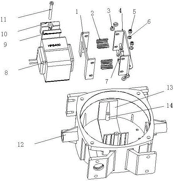
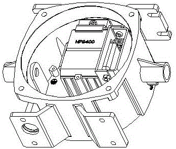
[0023] Please also refer to figure 1 and figure 2 , a ballast fixing device provided in a specific embodiment of the present invention. It should be noted that the front, rear, left, and right directions mentioned in the present invention are defined by the front, rear, left, and right directions in which the ballast is in working state, that is, under normal circumstances, the side of the ballast fixing device that is adjacent to the installation surface (wall surface) is The back is opposite to the front, so as to determine the front, rear, left, and right directions of the ballast and its fixing device.

[0024] Such as figure 1 As shown, the ballast fixing device includes: a ballast box body 12, a square groove member 13 for placing and fixing the ballast 8 is arranged...


PUM


Abstract

The invention provides a fixing device of a ballast resistor. The fixing device of the ballast resistor comprises a ballast resistor box body, a square groove construction element, and a wedge block fixing assembly, wherein a cylindrical cavity is formed in the box body, the square groove construction element is arranged in the cylindrical cavity, the ballast resistor is arranged in the square groove construction element, and the wedge block fixing assembly is arranged between the ballast resistor and the square groove construction element and fixes the ballast resistor and the square groove construction element. The fixing device of the ballast resistor further comprises buffer devices which are respectively arranged at the left side and at the right side of the ballast resistor, wherein the buffer devices are used for limiting the displacement of the ballast resistor. The fixing device of the ballast resistor is reliable in fixation simple in structure, easy to operate, and capable of controlling the displacement distance of the ballast resistor, enabling the ballast resistor to move within an allowable range, avoiding that a left top plate and a right top plate are damaged, and effectively guaranteeing safety of the ballast resistor. The invention further provides a ballast resistor assembly with the fixing device.

Description

technical field [0001] The invention relates to a high-power lamp, more specifically, to a ballast fixing device and a ballast assembly in the high-power lamp. Background technique [0002] At present, ballasts for lamps above 250W are installed and fixed by wedges, which can well compress the ballasts in the up and down and front and rear directions to prevent the movement of the ballasts, but they are not fixed in the left and right directions. The above ballasts are relatively heavy, and when the package falls, the impact force is very large. Even if the shell is equipped with a retaining bone, the retaining bone may be broken when the package falls, causing the ballast to break in the left and right directions. A large movement will cause a short circuit inside the electrical cavity, causing danger. And since ballasts of different sizes need to be installed in the case of the same ballast, directly setting the left and right ribs on the shell can only meet the needs of ...

Claims


Application Information

Patent Timeline
Patent Type & Authority Patents(China)
IPC IPC(8): F21V23/00
Inventor 周明杰李爱丽
Owner OCEANS KING LIGHTING SCI&TECH CO LTD
Why Eureka
Try Eureka