Numerical control lathe with automatic punching device

A drilling device and CNC lathe technology, applied in the direction of feeding device, boring/drilling device, drilling/drilling equipment, etc., can solve the problems of easy burnout of the drill bit, low production efficiency, uneven feed speed, etc., and achieve Low labor intensity, high production efficiency and simple operation

Inactive Publication Date: 2013-06-26
王布兴
View PDF6 Cites 1 Cited by
  • Summary
  • Abstract
  • Description
  • Claims
  • Application Information

AI Technical Summary

Problems solved by technology

When drilling a larger hole, it is necessary to add an afterburner rod to the handwheel of the tailstock before drilling, which is very inconvenient and labor-intensive and time-consuming for workers.
Especially if the feed speed is uneven, the drill bit is easy to burn out, and the life of the drill bit is greatly shortened
In addition, workers need to grind the drill bit frequently, which will consume unnecessary man-hours and lower production efficiency

Method used


Image

  • Numerical control lathe with automatic punching device
  • Numerical control lathe with automatic punching device

Examples


Embodiment Construction

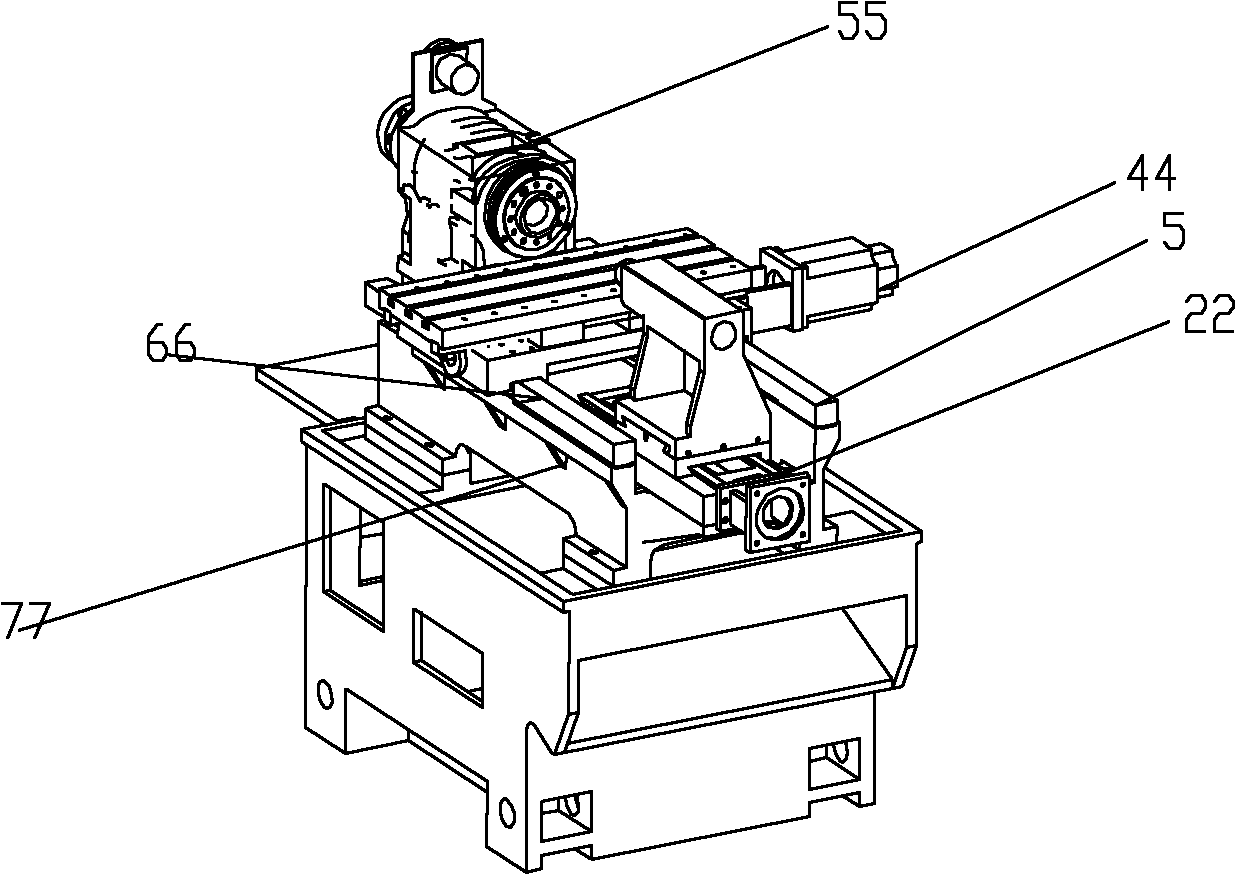
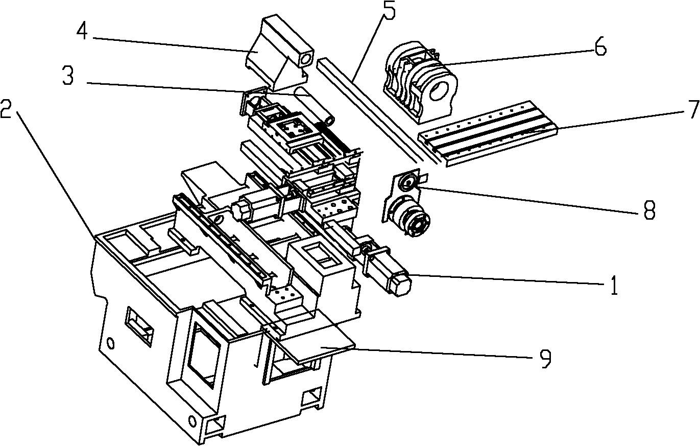
[0013] The present invention comprises machine base 2 and bed 77, and bed 77 one end is provided with tailstock 4, and the other end is provided with encoder seat 8, and tailstock 4 is mainly made up of tailstock body and tailstock sleeve 3, and tailstock passes tailstock The seat guide rail 5 is installed on the bed, and the tailstock sleeve 3 is installed in the round hole of the tailstock. The left and right linear guide rails 66 are arranged on the bed on both sides of the tailstock and the encoder seat 8, and a drag plate is arranged above the linear guide rail 66. The bed below the carriage is provided with a motor base 44, the top of the encoder base 8 is provided with a head box 6, the bed is provided with a motor base 55, the front end of the motor base is provided with a servo motor 1, and the middle part of the bed is provided with a slidable The small supporting plate 7, the tailstock guide rail 22 links to each other with the small supporting plate.

[0014] And b...


PUM


Abstract

A numerical control lathe with an automatic punching device in particular relates to structural improvement of a tail seat punching device of a numerical control lathe. The numerical control lathe with the automatic punching device is convenient to operate, low in labor intensity, high in production efficiency and high in drilling accuracy. The numerical control lathe with the automatic punching device comprises a machine seat, a lathe body and a tail seat, wherein the tail seat is positioned at one end of the lathe body, a lathe head is arranged at the other end of the lathe body, the tail seat is mainly composed of a tail seat guide rail, a tail seat carriage plate, a tail seat body, a tail seat sleeve and a hydraulic oil cylinder, the tail seat is installed on the lathe body through the tail seat guide rail, the tail seat sleeve is positioned in a round hole of the tail seat, a left linear guide rail or change rail and a right linear guide rail or change rail are arranged on the lathe body on two sides of the tail seat and the lathe head, the carriage plate is positioned above the linear guide rails, a motor seat is arranged on the lathe body under the carriage plate, the lathe head is arranged above the lathe body, the motor seat is positioned on the lathe body, a servo motor is arranged at the front end of the motor seat, the slidable tail seat carriage plate is arranged in the middle of the lathe body, the tail seat guide rail is connected with the tail seat carriage plate, and the tail seat body is connected with the tail seat carriage plate. The numerical control lathe is simple to operate and high in production efficiency.

Description

technical field [0001] The invention belongs to the field of design and manufacture of numerically controlled lathes, and in particular relates to an improvement of the structure of a tailstock punching device of a numerically controlled lathe. [0002] Background technique [0003] CNC machine tools generally include a machine base, a bed, and a tailstock. The device on the tailstock can be used for drilling and reaming. When the workpiece is drilled using the rear tailstock, the worker needs a lot of force to drill; especially When punching, you need to manually move the tailstock, tighten it before punching. Also need to add an afterburner bar on the handwheel of tailstock and drill again when drilling big hole again, very inconvenient during drilling, and workman's effort is time-consuming. Especially if the feed rate is uneven, the drill bit is easy to burn out, and the life of the drill bit is greatly shortened. In addition, workers need to grind the drill bit frequ...

Claims


Application Information

Patent Timeline
IPC IPC(8): B23B43/02B23Q5/34
Inventor 王布兴
Owner 王布兴
Why Eureka
Try Eureka