
Drawing method for hollow silicon core

A technology of hollow silicon core and manufacturing method, which is applied in chemical instruments and methods, silicon compounds, inorganic chemistry, etc., can solve the problems of increased fracture or collapse of silicon cores, inability to grow silicon cores, and large impact of cracks, etc., and achieve artificial Comprehensive low cost, rapid growth, and improved production efficiency

Active Publication Date: 2015-05-13
LUOYANG JINNUO MECHANICAL ENG
View PDF1 Cites 0 Cited by
  • Summary
  • Abstract
  • Description
  • Claims
  • Application Information

AI Technical Summary

Problems solved by technology

[0007] At present, there are wire-cut square silicon cores on the market. Due to the wire-cutting process, the crystal is subjected to micro-shocks in diamond wire-cutting, so that there are many tiny cracks in the finished square silicon core that are difficult to detect with the naked eye. The instantaneous impact on the cracks is large, which greatly increases the amount of fractures or collapses during the growth of the silicon cores. In the light cases, the group of silicon cores cannot grow, and in severe cases, the furnace will be shut down. Then, large-diameter silicon cores are used for lap joints. The rapid growth of polycrystalline rods and the improvement of the strength of the silicon core itself have become a technical barrier that is difficult for those skilled in the art to overcome; however, how to increase the diameter of the silicon core is also a long-term demand for those skilled in the art

Method used


Image

  • Drawing method for hollow silicon core
  • Drawing method for hollow silicon core
  • Drawing method for hollow silicon core

Examples


Embodiment Construction

[0036] The present invention is further described below in conjunction with embodiment; The following embodiment is not for the limitation of the present invention, only as the mode of supporting the realization of the present invention, any equivalent structural replacement within the technical framework disclosed in the present invention, all is the present invention. the scope of protection of the invention;

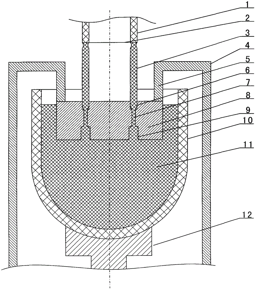
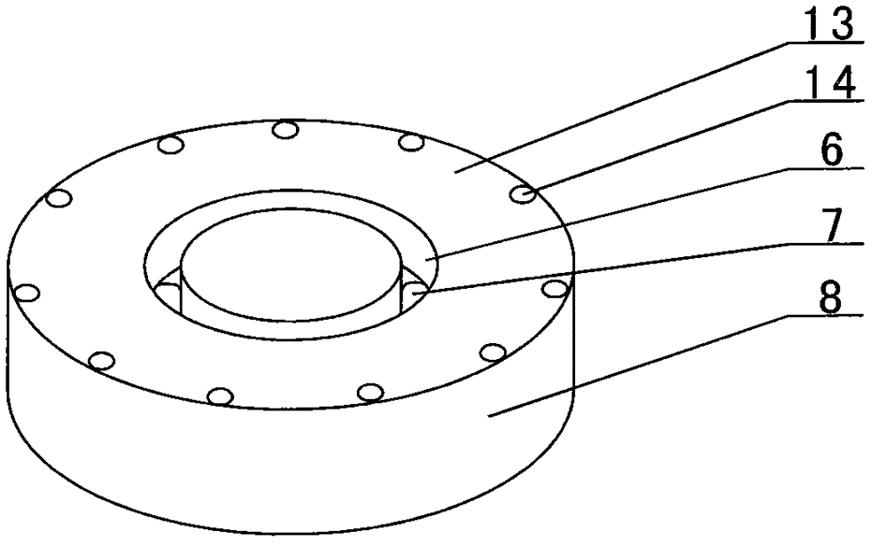
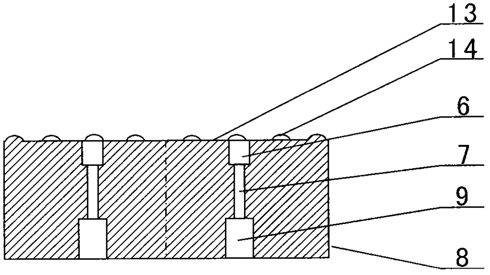
[0037] combined with figure 1 Or the drawing method of hollow silicon core described in 2 or 3, described drawing method comprises equipment, and described equipment comprises crucible 10 and heating mantle 4 for melting crystal 11; Die structure; the guide mode structure of the drawn tubular silicon core 3 is mainly used to realize the shape of the hollow silicon core; the crucible 10 and the heating jacket 4 for melting the crystal 11 are provided with heating at the outer interval of the crucible 10 Cover 4, the distance between the crucible 10 and the heating jac...


PUM


Abstract

The invention discloses a drawing method for a hollow silicon core. The drawing method for a hollow silicon core comprises a crucible (10) and a heating sleeve (4) for melting a crystal (11), and a guide die structure for drawing a tubular silicon core (3). The drawing method comprises the following steps of: A, placing materials in the crucible; B, heating the crucible to melt the crystal materials; C, drawing the tubular silicon core; and D, discharging the finished product. During the subsequent use of the hollow silicon core in the drawing method disclosed by the invention, the defect of small diameter of the existing solid square silicon core or circular silicon core is effectively overcome; the purpose of rapidly growing a polycrystalline rod is realized by the hollow silicon core having a weight which is equal to or slightly greater than the weight of the solid silicon core; and the method for drawing the silicon core disclosed by the invention is simple to cost, and capable of greatly saving enterprise cost.

Description

【Technical field】 [0001] The invention relates to a hollow silicon core, in particular the invention relates to a method for drawing a hollow silicon core of polysilicon or other crystalline materials. 【Background technique】 [0002] It is known that the silicon core bonding technology is a very important technology in the process of producing polysilicon by the Siemens method, and it is mainly used in a link of polysilicon production, that is, the reduction reaction process. The principle of the reduction reaction process is: the reduction reaction is carried out in a closed reduction furnace, and several closed loops are formed by lapping silicon cores in the reduction furnace before loading the furnace, which is the "bridge" in the jargon. "; each closed circuit is formed by two vertical silicon cores and a horizontal silicon core to form a "∏"-shaped structure; the two vertical silicon cores of each closed circuit are respectively connected to two electrodes on the botto...

Claims


Application Information

Patent Timeline
Patent Type & Authority Patents(China)
IPC IPC(8): C01B33/021
Inventor 刘朝轩王晨光
Owner LUOYANG JINNUO MECHANICAL ENG
Learn More