Temperature and humidity control system

A temperature and humidity control and control system technology, applied in heating and ventilation control systems, heating and ventilation safety systems, household heating, etc. Simple way to effect

Active Publication Date: 2013-06-12
GREE ELECTRIC APPLIANCES INC
View PDF6 Cites 8 Cited by
  • Summary
  • Abstract
  • Description
  • Claims
  • Application Information

AI Technical Summary

Problems solved by technology

[0004] The main purpose of the present invention is to provide a temperature and humidity control system to solve the problem that the independent control of temperature and humidity in one area cannot be simply realized

Method used


Image

  • Temperature and humidity control system
  • Temperature and humidity control system
  • Temperature and humidity control system

Examples


Embodiment Construction

[0022] It should be noted that, in the case of no conflict, the embodiments in the present application and the features in the embodiments can be combined with each other. The present invention will be described in detail below with reference to the accompanying drawings and examples.

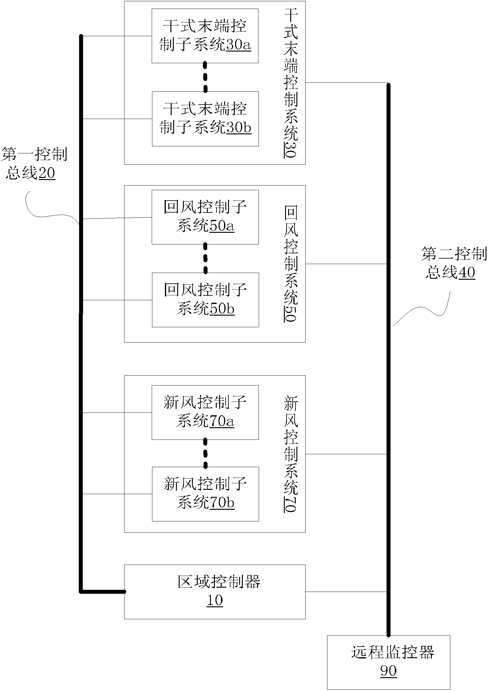
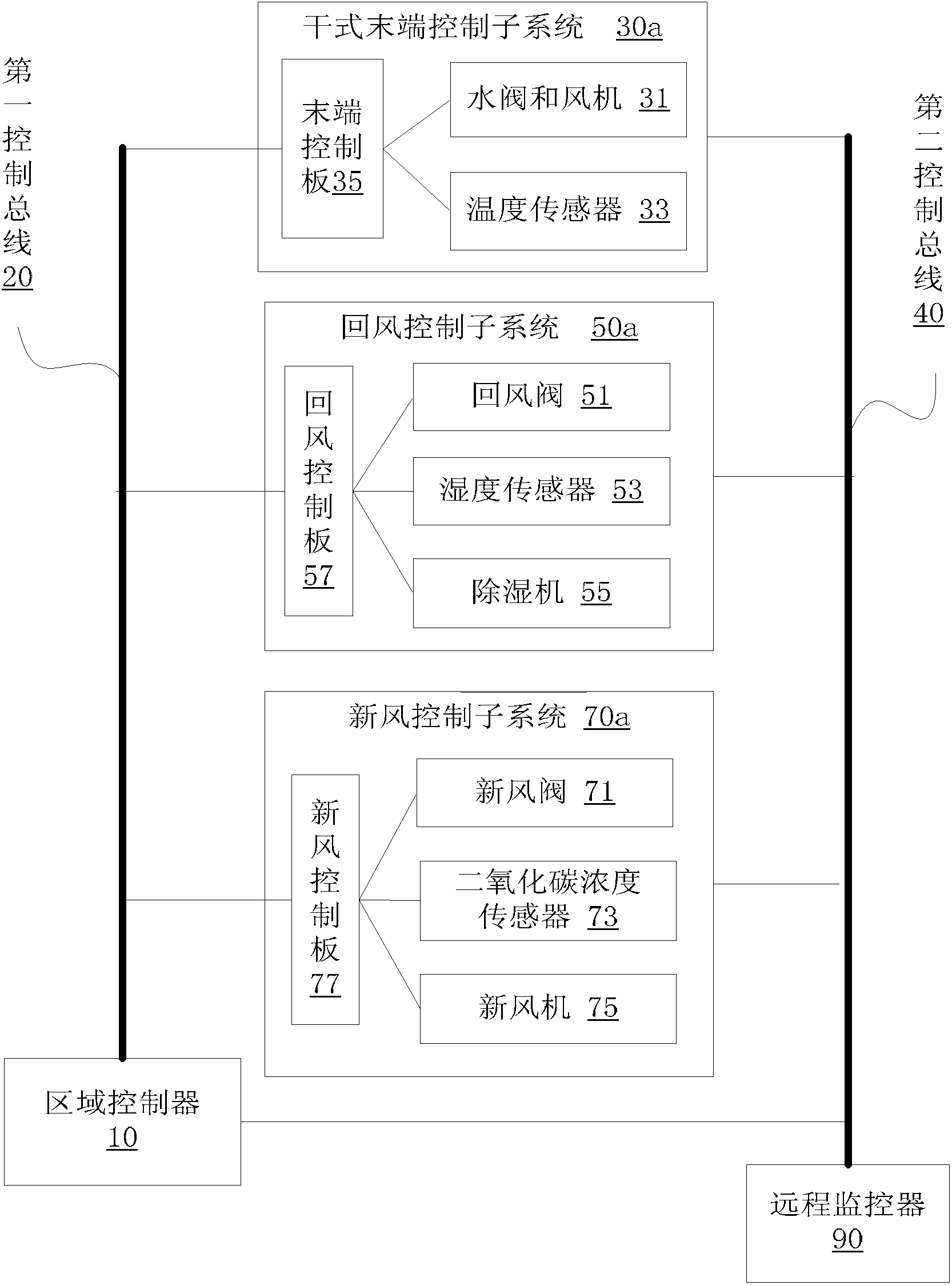
[0023] figure 1 is a block diagram of the temperature and humidity control system according to the first embodiment of the present invention, such as figure 1 As shown, the system includes: a terminal control system 30, a return air control system 50 and a fresh air control system 70, wherein the terminal control system 30 includes a terminal control subsystem 30a and a terminal control subsystem 30b; the return air control system 50 includes a return air The control subsystem 50a and the return air control subsystem 50b; the fresh air control system 70 includes a fresh air control subsystem 70a and a fresh air control subsystem 70b.

[0024] The system also includes a regional controller 10,...


PUM


Abstract

The invention discloses a temperature and humidity control system. The system comprises a first control bus, a zone controller, a second control bus and a remote monitor, wherein the zone controller respectively controls a dry type end control sub system, a return air control sub system and a fresh air control sub system through the first control bus; and the remote monitor respectively monitors the operating states of a dry type end control system, a return air control system, a fresh air control system and the zone controller through the second control bus, wherein the dry type end control system comprises at least one dry type rear end control sub system, the return air control system comprises at least one return air control sub system, and the fresh air control system comprises at least one fresh air control sub system. By utilizing the system, a communication of two control buses is adopted, one zone controller controls the sub systems in one zone, and one remote monitor monitors the zone controller and control systems in the corresponding zone; and the system is flexible in networking, easy to expand and simple in communication mode.

Description

technical field [0001] The invention relates to the field of air conditioners, in particular to a temperature and humidity control system. Background technique [0002] At present, many areas, such as offices, shopping malls, apartments or hotels, need to control the temperature and humidity of the entire area, that is, it is necessary to control the specific temperature and humidity adjustment equipment in one or more areas. However, the existing The complex control method and poor reliability often make the temperature and humidity control effect of a certain position or a certain room in a region poor; in addition, when adding a new controlled unit in the region, for example, in the unified control of a building In the system, when the function of unified control of another building is added, the expansion ability is poor. [0003] Aiming at the problems of complex control mode and poor expansion ability of the regional temperature and humidity control system in the rela...

Claims


Application Information

Patent Timeline
Patent Type & Authority Applications(China)
IPC IPC(8): F24F11/00
Inventor 谭国飞文武明开云任鹏夏飞
Owner GREE ELECTRIC APPLIANCES INC
Why Eureka
Try Eureka