
Display device and backlight module thereof

A backlight module and color light technology, which is applied to lighting devices, fixed lighting devices, components of lighting devices, etc., can solve the problem of uneven brightness and chromaticity of backlight modules, and achieve the effect of improving brightness and uneven chromaticity.

Inactive Publication Date: 2013-06-12
AU OPTRONICS CORP
View PDF4 Cites 22 Cited by
  • Summary
  • Abstract
  • Description
  • Claims
  • Application Information

AI Technical Summary

Problems solved by technology

[0005] The present invention is to provide a display device and its backlight module, so as to improve the problems of brightness and uneven chromaticity of the existing backlight module

Method used


Image

  • Display device and backlight module thereof
  • Display device and backlight module thereof

Examples


Embodiment Construction

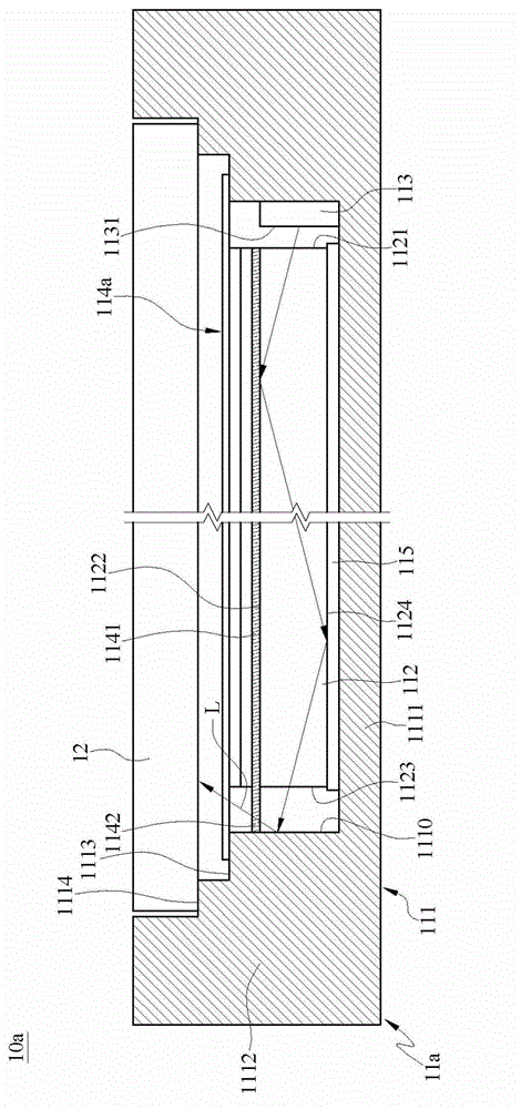
[0036] The present invention will be described in detail below in conjunction with the accompanying drawings and specific embodiments, but not as a limitation of the present invention.

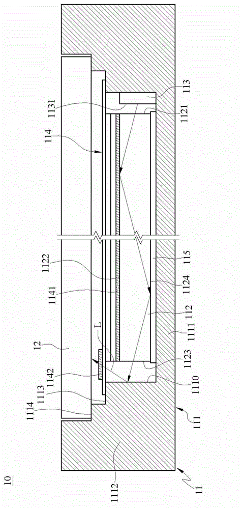
[0037] Please refer to figure 1 , figure 1 is a structural cross-sectional view of a display device according to an embodiment of the present invention.

[0038] The display device 10 in this embodiment is an example of a tablet computer or a display device in a liquid crystal screen, but it is not limited thereto. The display device 10 includes a backlight module 11 and a display panel 12 .

[0039] The backlight module 11 includes a frame body 111 , a light guide plate 112 , a light source 113 and an optical film set 114 .

[0040] The frame body 111 includes a load base 1111 and at least one wall 1112 erected on the periphery of the load base 1111 . The cross section of the wall 1112 is roughly a stepped shape. The wall 1112 has a first bearing platform 1113 and a second bearing platfor...


PUM


Abstract

The invention relates to a backlight module comprising a frame, a light guide plate, a light source and an optical film assembly. The light guide plate has a light entering surface and a light exiting surface, and is arranged in the frame. The light source is positioned in the frame and faces the light entering surface. Light emitted from the light source is non-white light. The optical film assembly is disposed on the light exiting surface and includes a first color conversion layer and a second color conversion layer. At least a part of the light emitted from the light source passe through the second color conversion layer and not the first color conversion layer. The first color conversion layer and the second color conversion layer are used for converting the light emitted from the light source from the non-white light into white light. The backlight module of the invention helps to solve problems that a conventional backlight module is uneven in brightness and chroma.

Description

technical field [0001] The invention relates to an electronic device, especially a display device with a backlight module. Background technique [0002] The rapid progress of the multimedia society is mostly benefited from the rapid development of semiconductor devices or display devices. As far as display components are concerned, cathode display tubes (or called image tubes, Cathode Ray Tube, CRT) have been monopolizing the display market due to their excellent display quality and economy. However, CRT-type displays have the problems of being too large and consuming too much energy. For the requirements of high image quality, low power consumption, thin mass production, low-voltage drive, and small size, CRT-type displays are obviously unable to achieve this. Require. In view of this, liquid crystal display (Liquid Crystal Display, referred to as LCD) will have great advantages, and LCD has been widely used in medium and small portable TVs, video phones, camcorders, note...

Claims


Application Information

Patent Timeline
Patent Type & Authority Applications(China)
IPC IPC(8): F21S8/00F21V9/10G02F1/13357F21Y101/02F21V9/40F21Y113/13F21Y115/10
Inventor 林义文
Owner AU OPTRONICS CORP
Learn More