Magnetorheological Flow Control Valve
A flow control valve, magnetorheological technology, applied in valve details, valve device, valve operation/release device, etc., can solve the problems that the flow control cannot be changed, it is difficult to achieve stepless control, and the product consistency is poor. The effect of simple structure, wide range and large pressure range
- Summary
- Abstract
- Description
- Claims
- Application Information
AI Technical Summary
Problems solved by technology
Method used
Image
Examples
Embodiment Construction
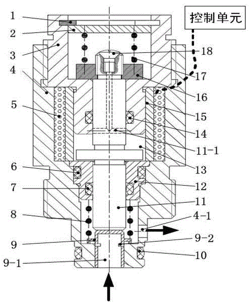
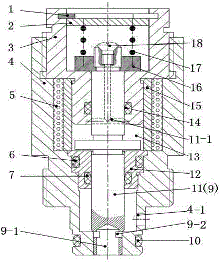
[0011] attached by figure 1 As shown: the magnetorheological flow control valve includes: circlip 1, upper end cover 2, upper valve body 3, lower valve body 4, coil 5, lower thrust spring 8, valve core 9, thrust shaft 11, inner valve body 12 , working cavity 13, magnetic isolation sleeve 15, spring seat 16, upper thrust spring 17, sealing bolt 18 and multiple rubber sealing rings (6, 7, 10, 14). The upper end cover 2 is set inside the upper valve body 3, the upper end of the upper end cover 2 is provided with a retaining spring 1, and the lower end is provided with an upper thrust spring 17 in a compressed state, so that the relative position between the upper end cover 2 and the upper valve body 3 fixed. The lower end of the upper thrust spring 17 is arranged on the spring seat 16, and the spring seat 16 is fixed on the uppermost end of the thrust shaft 11 through threaded connection, and a rubber sealing ring 14 is arranged between the thrust shaft 11 and the upper valve bo...
PUM
 Abstract
Description
Claims
Application Information
 - R&D
- Intellectual Property
- Life Sciences
- Materials
- Tech Scout
- Unparalleled Data Quality
- Higher Quality Content
- 60% Fewer Hallucinations
Browse by: Latest US Patents, China's latest patents, Technical Efficacy Thesaurus, Application Domain, Technology Topic, Popular Technical Reports.
© 2025 PatSnap. All rights reserved.Legal|Privacy policy|Modern Slavery Act Transparency Statement|Sitemap|About US| Contact US: help@patsnap.com


