Stone compaction mechanism of stone saw machine

A stone sawing machine and stone technology, which is applied to stone processing tools, stone processing equipment, work accessories, etc., can solve the problems of stone breaking and cutting accuracy, and achieve high processing accuracy, low scrap rate, and ideal processing effect. Effect

Inactive Publication Date: 2015-12-09
佛山市顺德区悍天睿数控机械有限公司
View PDF11 Cites 0 Cited by
  • Summary
  • Abstract
  • Description
  • Claims
  • Application Information

AI Technical Summary

Problems solved by technology

The feature of this structure is that the stone is clamped by the upper and lower sets of clamping devices, which can avoid the rock from shaking left and right, and facilitate the cutting and processing of the stone by the stone saw machine; however, when the structure processes relatively large stones , it is difficult to clamp the stone firmly only through the clamping mechanism on the left and right sides, and the stone will jump due to its own shaking or the vibration of the stone saw machine during the sawing process, which will lead to the breakage of the stone or the cutting accuracy. not tall

Method used


Image

  • Stone compaction mechanism of stone saw machine
  • Stone compaction mechanism of stone saw machine
  • Stone compaction mechanism of stone saw machine

Examples


Embodiment Construction

[0019] The present invention will be further described below in conjunction with the accompanying drawings and embodiments.

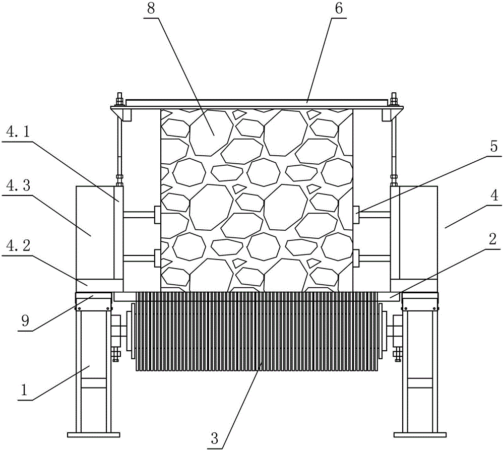
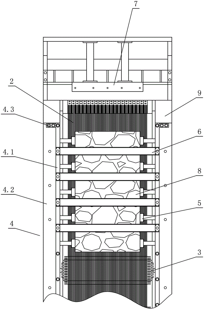
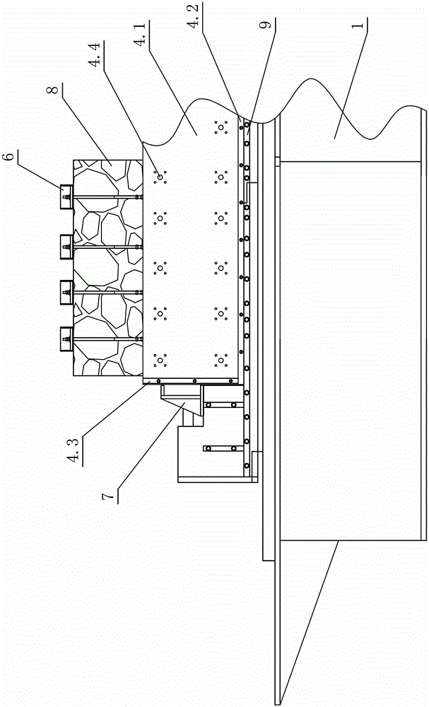
[0020] see Figure 1-Figure 4 , the stone compaction mechanism of this stone sawing machine includes a feeding table 2 with stones 8 placed, a feeding roller 3 connected between the left and right symmetrically arranged workbench bases 1, and the workbench base 1 A guide rail (marked in the figure) and a side pressing stone frame 4 are arranged on the upper side, which is characterized in that the side pressing stone frame 4 is slidably arranged on the guide rail, and a number of pressing stone blocks 5 for side pressing stone blocks 8 are arranged on the inside , the top of the side pressing stone frame 4 is also provided with the pressing stone crossbeam 6 of pressing solid stone 8 from top to bottom.

[0021] The side pressure stone frame 4 is composed of a side plate 4.1, a bottom plate 4.2 and a rib plate 4.3; wherein the side of the side plate 4....


PUM


Abstract

The invention discloses a stone block compression mechanism of a stone sawing machine, which comprises a feeding workbench for placing stone blocks and a feeding drum connected with a workbench base that is arranged symmetrically right and left, wherein a guide rail and a lateral stone compression rack are arranged above the workbench base; the stone block compression mechanism is characterized in that the lateral stone compression rack is slidingly arranged on the guide rail; a plurality of stone compression blocks for laterally compression the stone blocks are arranged on the inner side of the lateral stone compression rack; and a stone compression cross beam for pressing the stone blocks from the top down is arranged above the lateral stone compression rack. According to the stone block compression mechanism, the lateral stone compression rack and the stone compression cross beam are adopted for pressing the peripheries of the stone blocks, so that the stone blocks can be placed on the feeding workbench evenly and firmly, and are free from displacement in a cutting process; the processing accuracy of the stone blocks is high; as the stone blocks are pressed and make rectilinear motion under pushing of a feeding mechanism, a pushing steel frame of the feeding mechanism is not required to be additionally fixed with the stone blocks; saw cutting and processing of stone can be achieved only by applying thrust on the stone blocks; and the stone block compression mechanism is simple and reasonable in structure and convenient to operate, and the stone blocks are mounted firmly.

Description

technical field [0001] The invention relates to a stone sawing machine, in particular to a stone pressing mechanism of the stone sawing machine. Background technique [0002] I disclosed a stone clamping structure of a stone sawing machine in Chinese Patent Document No. CN102133779A on July 27, 2011, which includes a stone conveying platform and a saw frame for sawing stones; the left and right sides of the stone conveying platform are provided with guide rails, The clamping device is slidably arranged on the guide rail; the guide rail at least includes an upper linear guide rail and a lower linear guide rail. The clamping device is set on the upper and lower linear guide rails on the left and right sides of the stone conveying platform through sliders: the sliders are slidably matched with the upper and lower linear guide rails through balls. The feature of this structure is that the stone is clamped by the upper and lower sets of clamping devices, which can avoid the rock...

Claims


Application Information

Patent Timeline
Patent Type & Authority Patents(China)
IPC IPC(8): B28D7/00B28D1/02
Inventor 周金生
Owner 佛山市顺德区悍天睿数控机械有限公司
Why Eureka
Try Eureka