
Anticollision device for cutting bed

An anti-collision device and cutting machine technology, applied in metal processing machinery parts, maintenance and safety accessories, metal processing equipment and other directions, can solve the problems of no immediate stop, no setting, manual reset, etc., to achieve protection and reasonable structural design , to achieve the effect of anti-collision protection

Active Publication Date: 2015-07-15
HANGZHOU ECHO SCI TECH
View PDF10 Cites 0 Cited by
  • Summary
  • Abstract
  • Description
  • Claims
  • Application Information

AI Technical Summary

Problems solved by technology

[0002] In the cutting equipment, there are not a few accidents caused by the operator. In many cases, the operator's hand or other parts entered the cutting area, and the equipment did not stop immediately, causing serious consequences. There are also some obstacles during the cutting process. Entering the cutting area will cause potential safety hazards, so the anti-collision device is particularly important. In some existing technologies, there is no corresponding protection structure for obstacle detection and protection of personnel and materials, and manual reset is required.
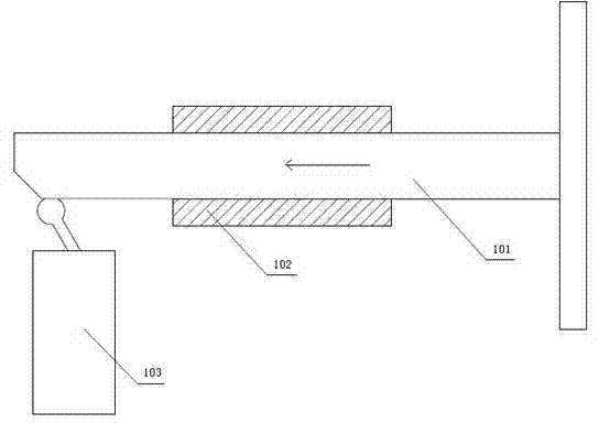
[0003] Existing protective devices such as Figure 1-Figure 2 As shown, a traditional bumper 101 is used to toggle the travel switch 103 to stop the equipment in an emergency to achieve the purpose of protecting personnel. This protection device has the following disadvantages: it cannot detect obstacles; it cannot protect materials and needs manual reset
[0004] Chinese Patent No. 200910252267.9 discloses an invention patent named "beam anti-collision device", which includes a crossbeam, the lower side of the beam is fastened with a screw nut pressure plate, and the lower end of the screw nut passes through the beam and is fixed with the disc spring cover Together, the upper end of the disc spring guide rod passes through the disc spring gland and is fixed with the screw nut pressure plate, the disc spring is limited between the lower end of the disc spring guide rod and the disc spring gland, and the screw nut pressure plate is installed through the switch bracket There is a travel switch, the patent is mainly to prevent damage to the screw rod caused by the collision between the beam and the workpiece, but because there is no structure related to the detection of personnel and obstacles, and there is no automatic reset function, so there are still the above defects
This patent is mainly through when an obstacle appears in front of the cutting bed, it first contacts with the block, when its pressure exceeds the force of the spring, the guide block on the sliding shaft starts to slide and touches the travel switch, and the travel switch stops the cutting machine The signal has the effect of anti-collision, but because there is no structure such as a through-beam photoelectric switch and a reflective photoelectric switch, the photoelectric switch cannot send a control signal, cannot detect obstacles, and cannot better protect personnel and materials. , so there are still the above defects

Method used


Image

  • Anticollision device for cutting bed
  • Anticollision device for cutting bed
  • Anticollision device for cutting bed

Examples


Embodiment Construction

[0025] The present invention will be further described below in conjunction with the accompanying drawings and embodiments.

[0026] see Figure 3 to Figure 9 , The present embodiment is used for the anti-collision device of cutting bed, mainly comprises bump plate 1, pendulum plate 2, extension spring 14, through-beam photoelectric switch 3, reflective photoelectric switch 4, anti-collision device 15 and reflector 18.

[0027] see Figure 3-Figure 7 , the touch plate 1 is installed on the moving base plate 10, the moving base plate 10 is fixed on the guide rail 6, the rotating shaft 9 is installed on the moving base plate 10, the slider 7 and the chute plate 5 are installed on the base plate 11, the pendulum plate 2 and the rotating shaft 9 connection, the guide pin 8 is fixed on the left end of the pendulum plate 2, the tension spring 14 is hung on the chute plate 5 and the guide rail 6, the through-beam photoelectric switch 3 is installed on the touch plate 1, and the refl...


PUM


Abstract

The invention relates to an anticollision device for a cutting bed, which is mainly used for the field of cutting / engraving / laser processing equipment and the like. The anticollision device for the cutting bed comprises a collision plate, guide rails, a swing plate, opposite type photoelectric switches, a reflective type photoelectric switch, pullback springs, sliding groove plates and a base plate, wherein the collision plate is connected onto the guide rails through a movable base plate; the swing plate is arranged on a rotation shaft; the opposite type photoelectric switches are arranged on the collision plate; the opposite type photoelectric switches are fixedly arranged on the sliding groove plates; the pullback springs are connected onto the sliding groove plates and the guide rails; and the sliding groove plates are arranged on the base plate. The anticollision device for the cutting bed realizes anticollision protection through the collision plate and the swing plate; the barrier detection is realized by the opposite type photoelectric switches; the material protection is realized by the reflective type photoelectric switch; and the automatic resetting of the device is realized by the pullback springs.

Description

technical field [0001] The invention relates to an anti-collision device, in particular to an anti-collision device for a cutting bed, which is mainly used in the fields of cutting, engraving, laser and other processing equipment. Background technique [0002] In the cutting equipment, there are not a few accidents caused by the operator. In many cases, the operator's hand or other parts entered the cutting area, and the equipment did not stop immediately, causing serious consequences. There are also some obstacles during the cutting process. Entering the cutting area will cause potential safety hazards, so the anti-collision device is particularly important. In some existing technologies, there is no corresponding protection structure for obstacle detection and protection of personnel and materials, and manual reset is required. [0003] Existing protective devices such as Figure 1-Figure 2 As shown, a traditional bumper 101 is used to toggle the travel switch 103 to stop ...

Claims


Application Information

Patent Timeline
Patent Type & Authority Patents(China)
IPC IPC(8): B23Q11/00
Inventor 方云科帅宝玉
Owner HANGZHOU ECHO SCI TECH
Learn More