Whole blisk high-efficiency compound milling disc milling device Hirth disc locking mechanism

An integral blisk and locking mechanism technology, applied in milling machine equipment, milling machine equipment details, metal processing and other directions, can solve the problems of insufficient locking force and difficult to guarantee control accuracy, and achieve large locking torque, accurate control, To achieve the effect of swing angle

Inactive Publication Date: 2016-01-20
NORTHWESTERN POLYTECHNICAL UNIV
View PDF4 Cites 0 Cited by
  • Summary
  • Abstract
  • Description
  • Claims
  • Application Information

AI Technical Summary

Problems solved by technology

Due to the surface-to-surface contact of this locking method, although locking at any angle can be achieved, the locking force is not enough and the control accuracy is difficult to guarantee. It is necessary to install an angle encoder on the final actuator for angle feedback, forming closed loop control system

Method used


Image

  • Whole blisk high-efficiency compound milling disc milling device Hirth disc locking mechanism
  • Whole blisk high-efficiency compound milling disc milling device Hirth disc locking mechanism
  • Whole blisk high-efficiency compound milling disc milling device Hirth disc locking mechanism

Examples


Embodiment Construction

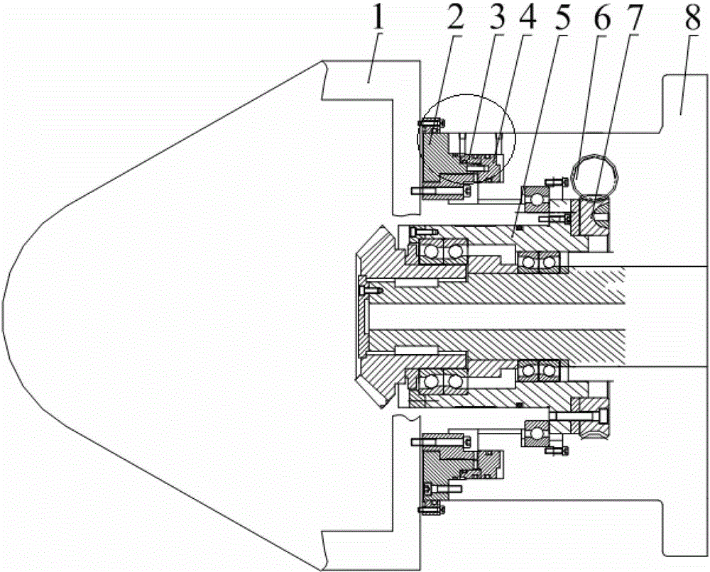
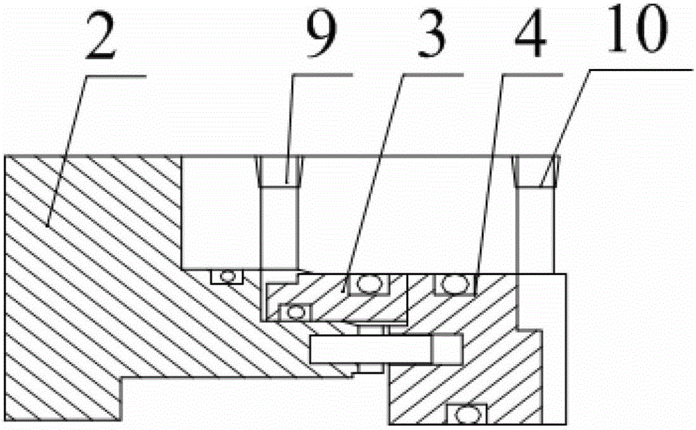
[0017] The following examples refer to Figure 1-7 .

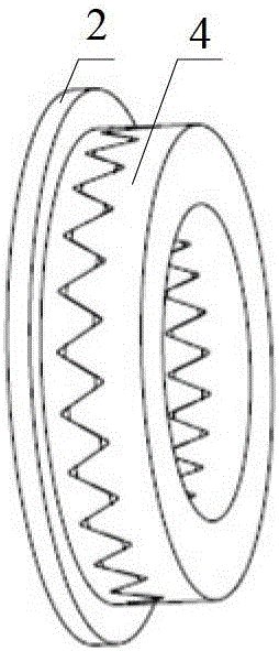
[0018] The hirth disc locking mechanism of the integrated blisk high-efficiency compound milling disc milling device of the present invention includes a disc milling box 1, an inner box 5, a worm 6, a worm wheel 7, an outer box 8, a left oil hole 9, and a right oil hole. Hole 10, servo motor 11, left chainring 2, push ring 3 and right chainring 4. The right side of the left chainring 2 has rat teeth, the left side of the right chainring 4 has rat teeth, the left chainring 2 and the right chainring 4 mesh with each other, and the two end faces of the push ring 3 are respectively connected with the left chainring. 2 is matched with the right chainring 4. The left chainring 2 is installed on the disk milling box 1, the right chainring 4 is installed and connected to the outer box 8, the turbine 7 is fixed on the inner box 5 with bolts, and the inner box 5 is fixed with the disk milling box 1. Connected, the servo motor 11 ...


PUM


Abstract

The invention discloses a mouse tooth disk locking mechanism for an efficient and compound milling disk mill device of a blisk. The mouse tooth disk locking mechanism is used for solving the technical problem that an existing hydraulic locking mechanism for the efficient and compound milling disk mill device of the blisk is poor in locking force. The technical scheme is that the mouse tooth disk locking mechanism comprises a disk mill box body (1), an inner box body (5), a worm (6), a worm gear (7), an outer box body (8), a serve motor (11), a left side fluted disk (2), a push ring (3) and a right side fluted disk (4). The left side fluted disk (2) and the right side fluted disk (4) are meshed, and two end faces of the push ring (3) are respectively matched with the left side fluted disk (2) and the right side fluted disk (4). The mouse tooth locking mechanism can generate locking force through mesh between tooth faces between mouse disk teeth so as to be large in locking torque and meet high-rigidity and large-torque requirements in a disk milling process. Furthermore, the minimum scale division of three piece type end face fluted disks of the mouse tooth disk is 1 degree so as to achieve accurate control of a swing angle of the disk mill device.

Description

technical field [0001] The invention relates to a Hirth disk locking mechanism, in particular to a Hirth disk locking mechanism of an integral blisk high-efficiency compound milling disk milling device. Background technique [0002] The locking mechanism of the well-known high-efficiency compound milling disc milling device for integral blisks adopts a hydraulic method. The hydraulic locking mechanism includes a brake ring, a brake seat, a gland and a sealing ring. When the brake is tightened, high-pressure hydraulic oil is introduced from the oil chamber to push the brake ring to deform, thereby generating friction, and using the braking torque provided by the friction force to achieve locking. Due to the contact between the surfaces of this locking method, although locking at any angle can be achieved, the locking force is not enough, and the control accuracy is difficult to guarantee. It is necessary to install an angle encoder on the final actuator for angle feedback to...

Claims


Application Information

Patent Timeline
Patent Type & Authority Patents(China)
IPC IPC(8): B23C9/00B23Q5/00B23C3/18
Inventor 史耀耀辛红敏张军锋李志山张晓扬宁立群
Owner NORTHWESTERN POLYTECHNICAL UNIV
Why Eureka
Try Eureka