Instant trip mechanism for minitype circuit breaker

A technology of tripping mechanism and circuit breaker, applied in contact drive mechanism, circuit breaker with excessive current, overload protection circuit breaker, etc., can solve problems such as process problems

Inactive Publication Date: 2013-06-05
LSIS CO LTD
View PDF4 Cites 3 Cited by
  • Summary
  • Abstract
  • Description
  • Claims
  • Application Information

AI Technical Summary

Problems solved by technology

[0013] First, because MCCBs are classified into "B", "C" and "D" types according...

Method used


Image

  • Instant trip mechanism for minitype circuit breaker
  • Instant trip mechanism for minitype circuit breaker
  • Instant trip mechanism for minitype circuit breaker

Examples


Embodiment Construction

[0032] A detailed description will now be given of the exemplary embodiments with reference to the accompanying drawings. For brief description with reference to the drawings, the same or equivalent elements will be provided with the same reference numerals, and descriptions thereof will not be repeated.

[0033] Hereinafter, an instantaneous trip mechanism for a circuit breaker according to the present invention will be explained in more detail with reference to the accompanying drawings.

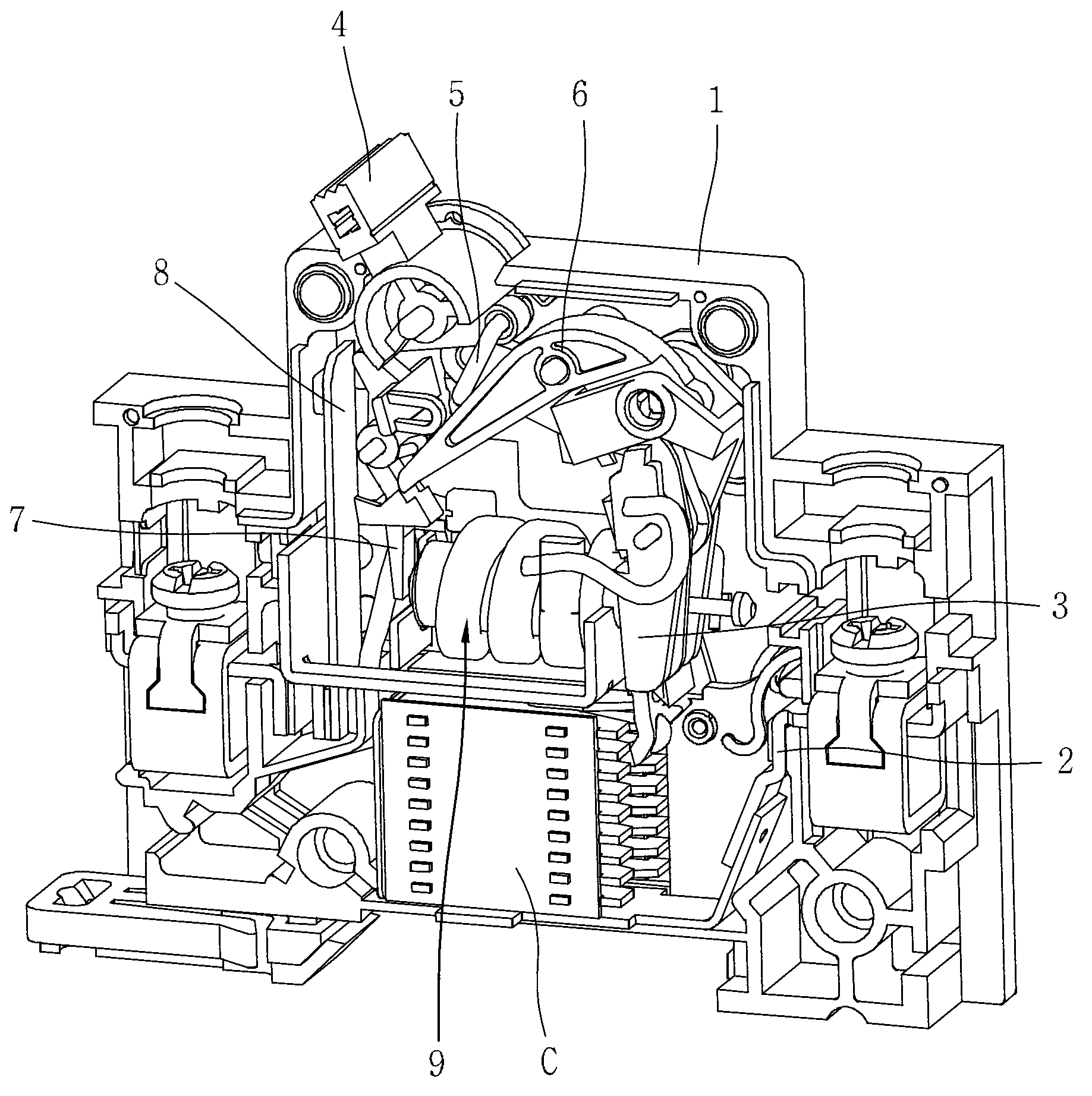
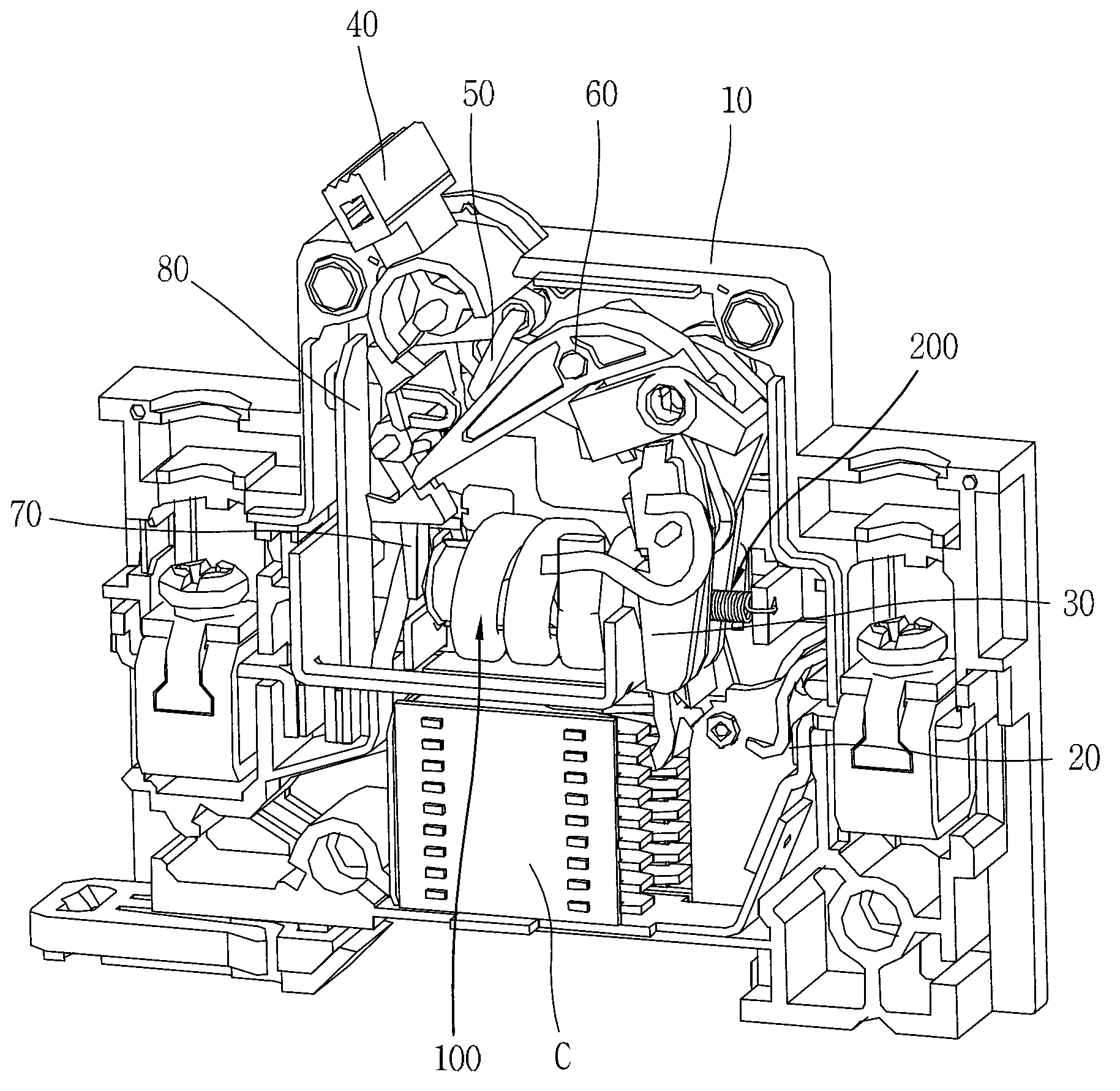
[0034] figure 2 is a perspective view showing the inside of a miniature molded case circuit breaker (MCCB) according to the present invention.

[0035] As shown in the figure, the small molded case circuit breaker with instantaneous trip mechanism according to the present invention includes: a fixed plate 20 installed at the lower end of the housing 10; The middle part, and is turned on / off by selectively contacting the fixed plate 20; the handle 40, which is installed on the upper end ...


PUM


Abstract

The invention discloses an instant trip mechanism for a minitype circuit breaker. Because a spring and an adjusting lever for changing spring elasticity are mounted on one side of a flexible center, motion current of the flexible center is changed, instant motion characters "B/C/D" can be changed and assembly procedures of products are simplified. When an instant motion curve is changed, the instant trip mechanism can easily select the instant characters, so that user convenience can be increased.

Description

technical field [0001] The present disclosure relates to a molded case circuit breaker, and more particularly, to an instantaneous trip mechanism for a miniature circuit breaker capable of controlling instantaneous action characteristics. Background technique [0002] Molded case circuit breakers (MCCBs) are used in low-voltage power systems to protect loads and equipment from accidental current damage. In the case of the mechanical type, the operating mechanism of the MCCB is performed by a bimetal and a solenoid. The circuit breaker is activated by the thermal action of the bimetal in the range of overcurrent protection. Here, the circuit breaker operates within the range of 1.13 to 2.5 times the rated current. The instantaneous current protection range refers to that which is greater than 3 times the rated current, and the amateur attraction principle (amateur attraction principle) of the electromagnetic coil is applied to it. [0003] According to the protection range...

Claims


Application Information

Patent Timeline
IPC IPC(8): H01H71/24
CPCH01H3/38H01H71/06H01H71/2472H01H71/505H01H71/52H01H73/045
Inventor 咸承珍
Owner LSIS CO LTD
Why Eureka
Try Eureka