Eureka AIR delivers breakthrough ideas for toughest innovation challenges, trusted by R&D personnel around the world.

Device for suppressing vibration of rolling mill

A rolling mill and vibration signal technology, which is applied in metal rolling, metal rolling, and keeping the rolling equipment in an effective state, etc., can solve the problems of the complex mechanical structure of the rolling mill, affecting the production output and economic benefits, and the many functions of the main drive control system.

Inactive Publication Date: 2013-05-29
UNIV OF SCI & TECH BEIJING
View PDF5 Cites 28 Cited by
  • Summary
  • Abstract
  • Description
  • Claims
  • Application Information

AI Technical Summary

Problems solved by technology

In actual production, when vibration occurs, temporary measures such as reducing speed, changing lubrication state or changing rolls are forced to improve the vibration state of the rolling mill, which seriously affects the production output and economic benefits
The reason is not only because the mechanical structure of the rolling mill is very complex, and the hydraulic roll gap control system and the main drive control system have many functions, but also because there are many process parameters in the rolling process, and various parameters are coupled and intertwined, so that the rolling mill presents an electromechanical Multi-state coupling vibration phenomenon in liquid boundary

Method used


Image

  • Device for suppressing vibration of rolling mill
  • Device for suppressing vibration of rolling mill
  • Device for suppressing vibration of rolling mill

Examples


Embodiment Construction

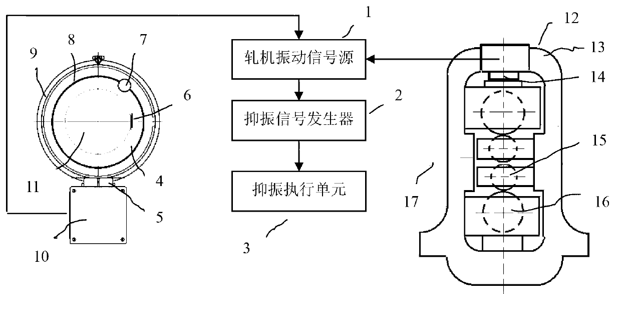
[0018] Such as figure 1 As shown, the structure of the rolling mill vibration suppression device of the present invention is composed of a rolling mill vibration signal source 1 , a vibration suppression signal generator 2 , a vibration suppression execution unit 3 and a rolling mill 12 .

[0019] When the rolling mill vibrates, the signal from the rolling mill vibration signal source 1 is introduced into the vibration suppression signal generator 2 to generate a vibration suppression damping signal, and the vibration suppression execution unit 3 is used to suppress the vibration of the rolling mill 12 .

[0020]

[0021] Such as figure 2 As shown, the principle of the present invention is that when the rolling mill is rolling a strip with thin gauge or large deformation resistance, the rolling mill will vibrate strongly. At first pick up the rolling mill torsional vibration signal, the rolling speed signal, the rolling mill vertical vibration signal and the rolling pressur...


PUM


Abstract

The invention belongs to the field of signal detection and automation control of rolling mills, and relates to a device for suppressing vibration of a rolling mill. The device for suppressing the vibration of the rolling mill is characterized by comprising a rolling mill vibration signal source, a vibration suppression signal generator, a vibration suppression actuating unit and the rolling mill, wherein the rolling mill vibration signal source is composed of rolling mill torsion vibration signals, rolling speed signals, rolling mill vertical vibration signals and rolling pressure signals, the vibration suppression signal generator is composed of a signal input module, a filter processing module, a phase recognition module, a vibration suppression signal module and a signal output module, and the vibration suppression actuating unit is composed of a main drive speed setter and a hydraulic roll gap setter. The device for suppressing the vibration of the rolling mill has the advantages that vibration suppression damping signals are generated by the vibration suppression signal generator according to the rolling mill vibration signal source and sent to the main drive speed setter and the hydraulic roll gap setter of the vibration suppression actuating unit so as to participate in control of the rolling mill to reduce the vibration energy of the rolling mill, so that the rolling mill can be prevented from vibrating severely, chatter marks on a roller and the surfaces of strips are eliminated, and therefore the surface quality of products is improved, and the on-line service life of the roller is prolonged.

Description

technical field [0001] The invention relates to the field of rolling mill signal detection and automatic control, in particular to a rolling mill vibration suppression device. Background technique [0002] For half a century, most rolling mills around the world have frequently experienced strong "ghost" vibrations when rolling strips with thin gauge or high deformation resistance, resulting in the formation of vibration marks on the strip and rolls, reducing the The surface quality of the strip and the online service life of the rolls may even cause accidents such as equipment, which seriously threatens the safe operation of the rolling mill. Many scholars and experts have done a lot of research on rolling mill vibration and achieved some results, but no universal device has been found to suppress rolling mill vibration. In actual production, when vibration occurs, temporary measures such as slowing down, changing the lubrication state or changing rolls are forced to improv...

Claims


Application Information

Patent Timeline
Patent Type & Authority Applications(China)
IPC IPC(8): B21B28/00
Inventor 闫晓强
Owner UNIV OF SCI & TECH BEIJING
Why Eureka
Eureka Blog
Learn More