
Speed changing box capable of automatically adjusting gear meshing clearance

A technology of automatic adjustment and transmission, applied in the direction of belt/chain/gear, transmission parts, mechanical equipment, etc.

Inactive Publication Date: 2013-05-15
徐红旗 +3
View PDF8 Cites 1 Cited by
  • Summary
  • Abstract
  • Description
  • Claims
  • Application Information

AI Technical Summary

Problems solved by technology

And do not rebound when encountering resistance

Method used


Image

  • Speed changing box capable of automatically adjusting gear meshing clearance
  • Speed changing box capable of automatically adjusting gear meshing clearance

Examples


Embodiment Construction

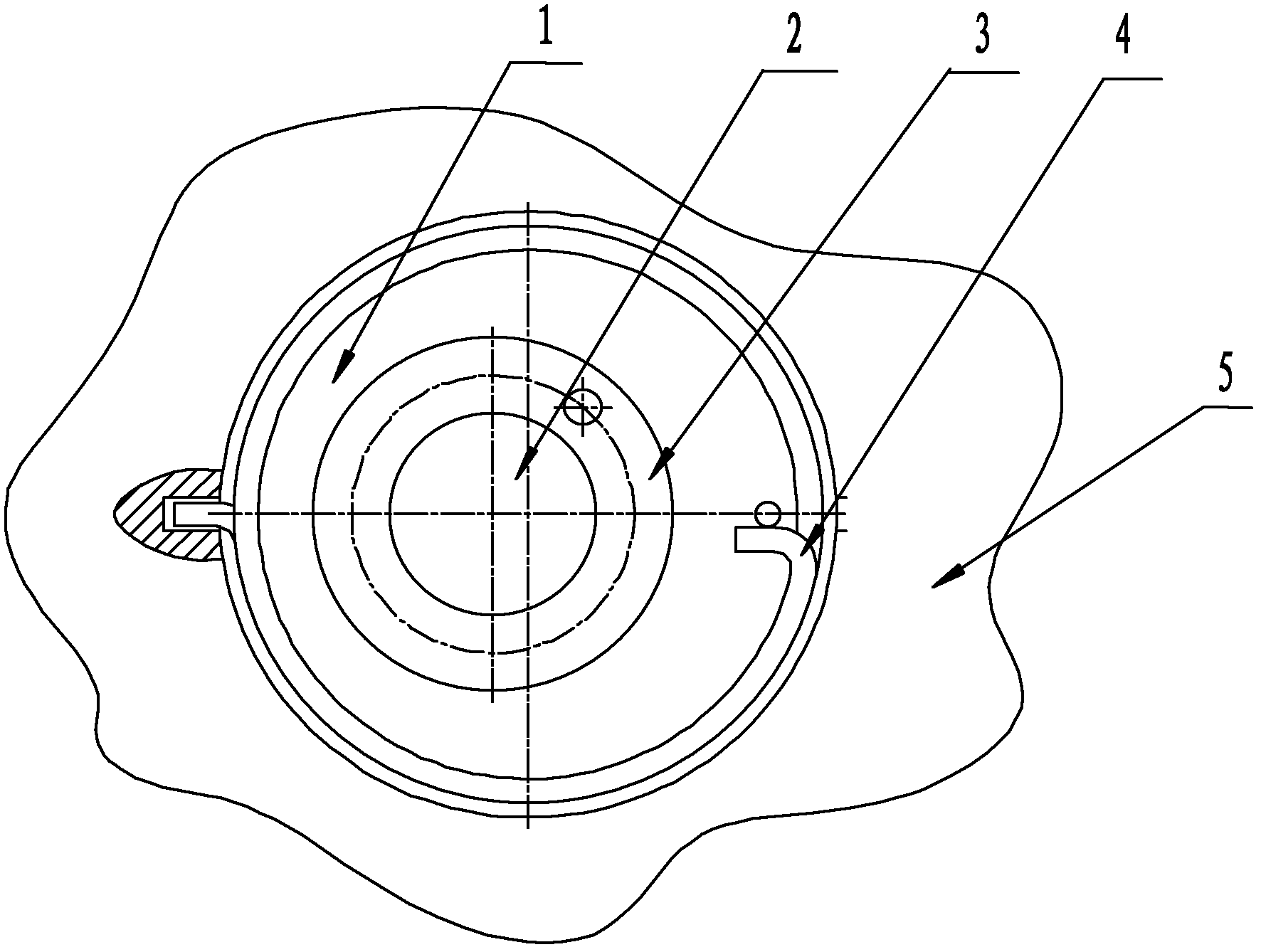
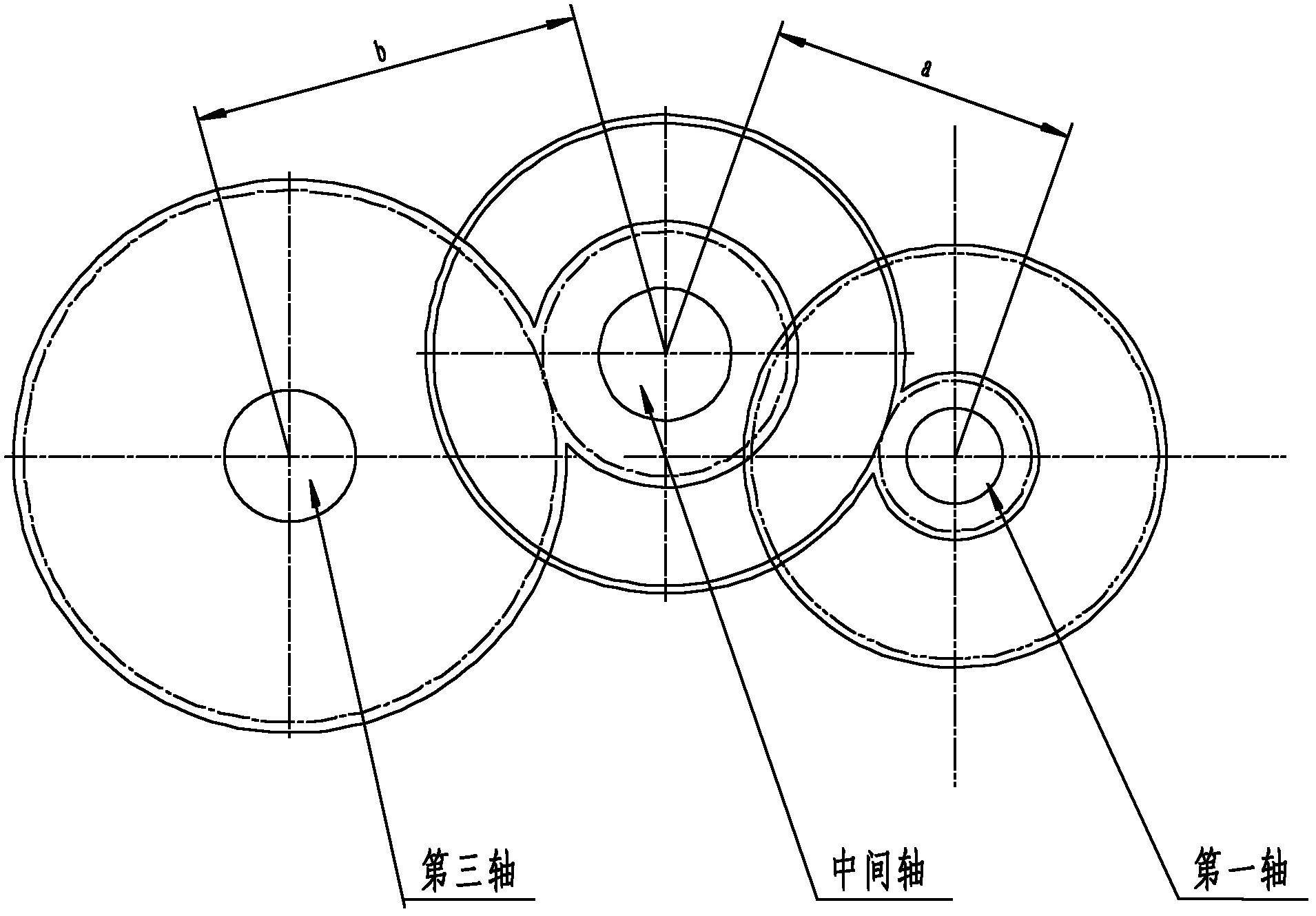
[0008] A gearbox for automatically adjusting the gear meshing gap provided by the present invention, the main components of the example mechanism include the first shaft, the third shaft, the intermediate shaft 2, the bearing 3, the eccentric sleeve 1, the torsion spring 4, the box body 5, etc. , when the gear wears and produces a gap, the torsion spring drives the eccentric sleeve to rotate counterclockwise ( figure 1 ), so that the position of the intermediate shaft moves down, reducing the wheelbase a between the intermediate shaft 2 and the first shaft and the wheelbase b between the intermediate shaft 2 and the third shaft, so as to achieve the purpose of reducing or even eliminating the meshing gap.

[0009] Among them, the bearing is a standard part, which can be selected according to the load; the manufacturing methods of the other eccentric sleeves, torsion springs, shafts, gears, boxes, etc. belong to the known technology, so they will not be explained here.


PUM


Abstract

The invention provides a speed changing box capable of automatically adjusting a gear meshing clearance. Main parts of a sample mechanism of the speed changing box mainly comprise a first shaft, a third shaft, a middle shaft 2, a bearing 3, an eccentric bushing 1, a torsional spring 4 and a box body 5. when a gear is abraded to form a clearance, the torsional spring drives the eccentric bushing to rotate in an anticlockwise mode, the position of the middle shaft is enabled to move downwards, the shaft distance a between the middle shaft 2 and the first shaft and the shaft distance b between the middle shaft 2 and the third shaft are reduced, and therefore goals of reduction of the meshing clearance and even elimination of the meshing clearance are achieved.

Description

technical field [0001] The invention relates to the mechanical equipment manufacturing industry, especially the numerical control machine tool industry. Background technique [0002] Since the feed and transmission system of CNC machine tools require high precision, it is difficult for the general meshing method to meet the precision requirements. In the past, springs or shims were used to eliminate meshing gaps, but each has its own defects. The thin-toothed-tooth adjustment method using springs needs to rely on spring force to transmit power, so it cannot be used in occasions with heavy loads; and the thin-tooth-tooth adjustment method using shims cannot automatically eliminate the gap, and the gearbox needs to be disassembled for adjustment ,Time-consuming. Therefore, it is not ideal to apply it to the feed and transmission system of CNC lathes, especially in the case of high precision requirements, the defects are more obvious. Contents of the invention [0003] The ...

Claims


Application Information

Patent Timeline
IPC IPC(8): F16H57/12
Inventor 徐红旗孙成波葛大伟主艳丽
Owner 徐红旗
Learn More