
Device for lowering the fuel consumption of the propulsion of a watercraft

A watercraft and power technology, applied in the direction of transportation and packaging, engine components, machines/engines, etc., can solve the problems of large inflow and resistance of the propeller, and achieve the effect of reducing the thickness of the section

Active Publication Date: 2013-05-15
BECKER MARINE SYST
View PDF7 Cites 7 Cited by
  • Summary
  • Abstract
  • Description
  • Claims
  • Application Information

AI Technical Summary

Problems solved by technology

[0003] However, the aforementioned previously known arrangement has a relatively high resistance to the propeller inflow, so that a corresponding reduction in drive power requirements is mainly found only in slower or heavier cargo ships, so the known arrangement is often Only used in this type of boat

Method used


Image

  • Device for lowering the fuel consumption of the propulsion of a watercraft
  • Device for lowering the fuel consumption of the propulsion of a watercraft
  • Device for lowering the fuel consumption of the propulsion of a watercraft

Examples


Embodiment Construction

[0081] In the various embodiments shown below, the same components have the same reference numerals.

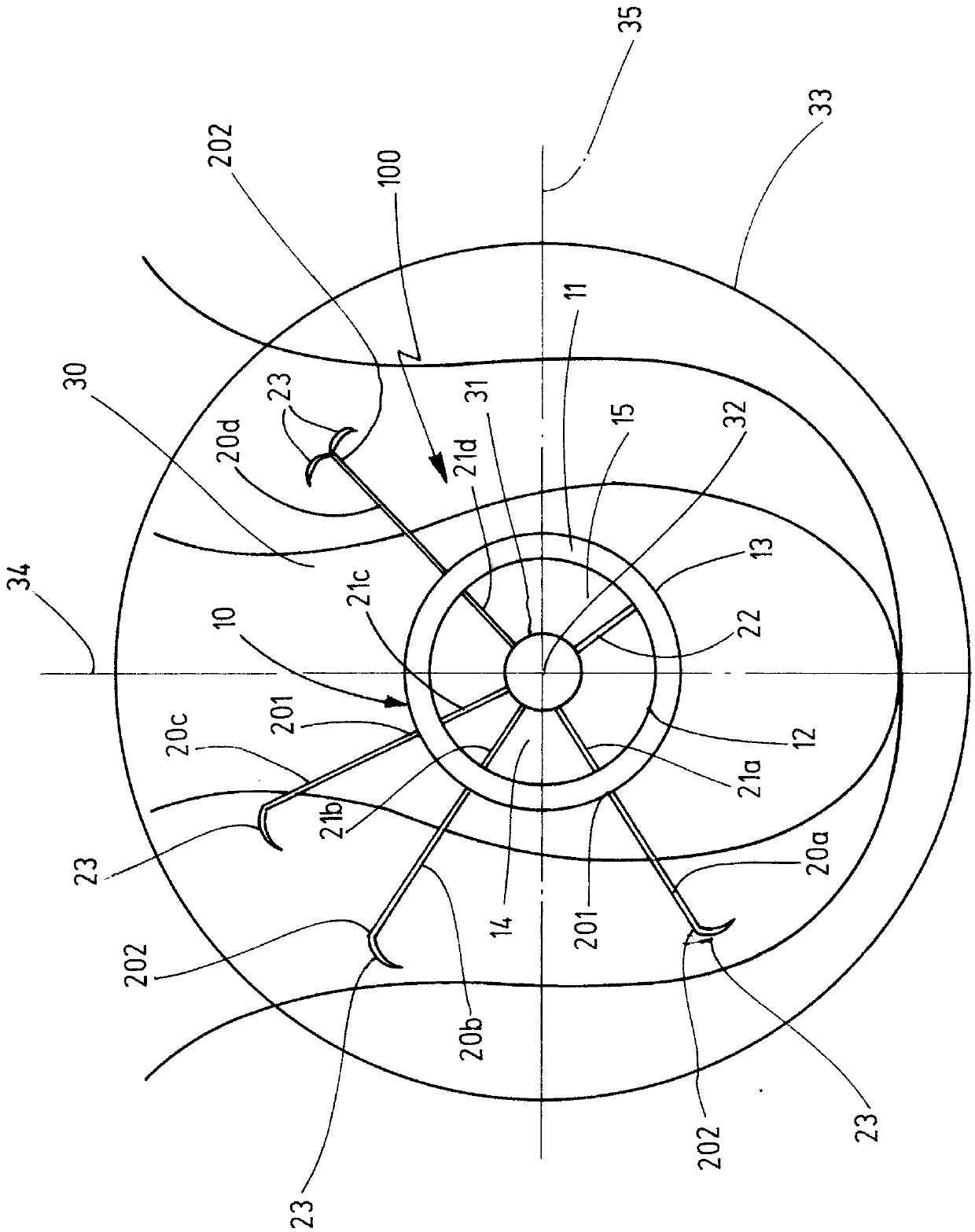
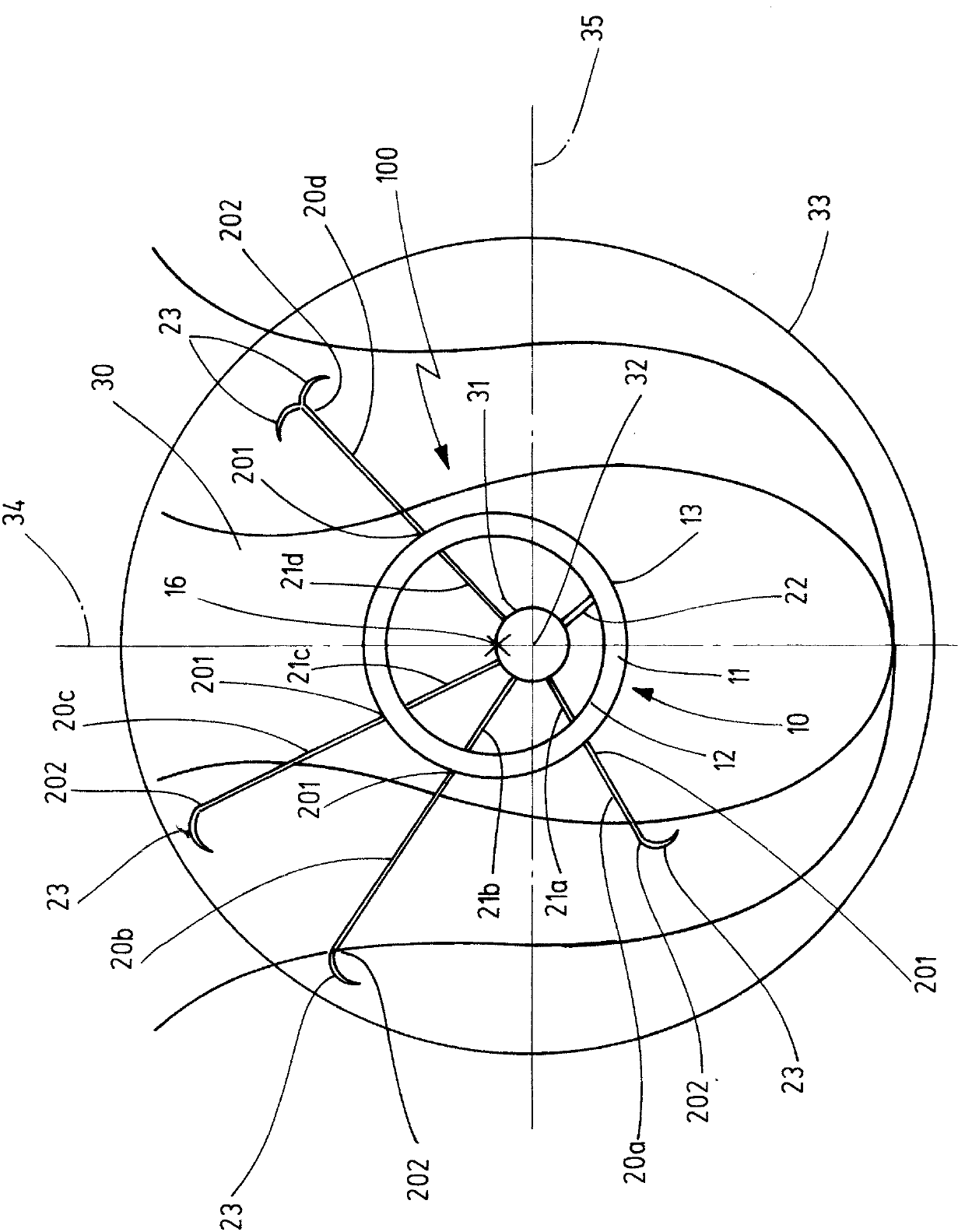
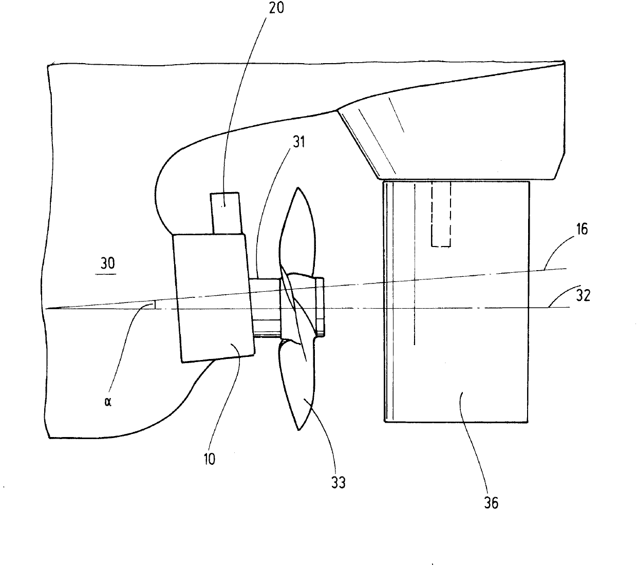
[0082] figure 1 A rear view of the lower rear area of ​​the hull 30 is shown. The bearing 31 is arranged as a shaft tube protruding from the hull 30 in a substantially horizontal direction from the stern. in figure 1 In the figure, the bearing 31 extends from or into the plane of the drawing. A propeller shaft (not shown in the figure) extending along the propeller axis 32 is installed in the bearing 31. in figure 1 In the figure, the propeller axis 32 also extends from or into the plane of the drawing. The propeller axis 32 at the same time forms the longitudinal axis of the front nozzle 10 arranged coaxially with the propeller axis 32. Since the front nozzle 10 in this exemplary embodiment is shown as a rotationally symmetric body, the propeller axis 32 also forms the rotation axis of the front nozzle 10 at the same time. The propeller 33 is only shown schematically as a p...


PUM


Abstract

The device (100) has outer fins (20a-20d) projecting in outward direction from a fore-nozzle (10). Ends (201) of the outer fins are fastened to the nozzle, and other ends (202) of the outer fins are designed as free end (202). End of inner fins (21a-21c) are fastened to an inner wall surface (12) of the nozzle. The outer fins or inner fins are arranged radially to a propeller axis of a propeller of a watercraft and designed as a sweptback fin. The outer fins are arranged in an extension of the inner fins. A fin end piece (23) protrudes on a suction side (203) of the outer fins.

Description

Technical field [0001] The invention relates to a device for reducing the driving power requirements of watercraft, especially ships. The device according to the invention is particularly suitable for improving the energy efficiency of watercraft drive systems. Background technique [0002] A device for reducing the driving power requirement of watercraft is known in the prior art. In EP2100808A1, such a device includes, for example, a fore-nozzle. The front nozzle is specifically installed at a close distance of the propeller or directly upstream of the propeller from the traveling direction of the ship. And, fins, namely (guide) fins or hydrofoils are provided in the front spout. The front spout basically has a flat conical cross-sectional shape, wherein the two openings, the water inlet and the water outlet are all configured as substantially circular openings, and the diameter of the water inlet is larger than the diameter of the water outlet. As a result, it is possible ...

Claims


Application Information

Patent Timeline
Patent Type & Authority Applications(China)
IPC IPC(8): B63H1/28B63H5/16
CPCY02T70/127B63H5/16F01D5/02B63H1/28B63B1/08
Inventor 德克·莱曼弗里德里希·密维斯
Owner BECKER MARINE SYST
Learn More