
Upper vehicle-body structure of vehicle

A body and vehicle technology, applied in the direction of upper structure, vehicle components, upper structure sub-assembly, etc., can solve the problems of inability to ensure the stability of curtain airbag deployment and the difference in expansion characteristics, so as to improve the rigidity of the body and reduce the vertical direction Width, the effect of securing the body mountability

Inactive Publication Date: 2013-05-15
MAZDA MOTOR CORP
View PDF7 Cites 7 Cited by
  • Summary
  • Abstract
  • Description
  • Claims
  • Application Information

AI Technical Summary

Problems solved by technology

However, in the curtain airbag in which the front airbag and the rear airbag are shared, if the installation position of the inflator is shifted in the front-rear direction relative to the approximately middle position in the front-rear direction of the curtain airbag, the front-seat airbag and the rear-seat airbag The supply timing of the air pressure supplied by the airbag for the rear seat is different, so the expansion characteristics of the airbag for the front seat and the airbag for the rear seat are different, and the deployment stability of the curtain airbag for both front and rear passengers may not be ensured.
[0010] In addition, in recent years, in vehicles equipped with openings such as sunroofs, there is a tendency to diversify the design of the vehicle, such as increasing the size of the opening or increasing the inclination angle of the windshield.

Method used


Image

  • Upper vehicle-body structure of vehicle
  • Upper vehicle-body structure of vehicle
  • Upper vehicle-body structure of vehicle

Examples


Embodiment 1

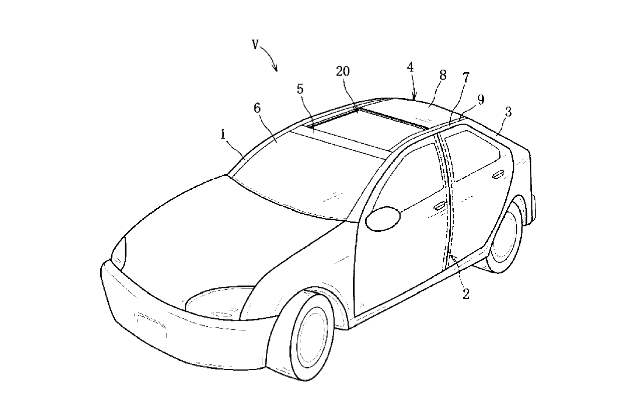
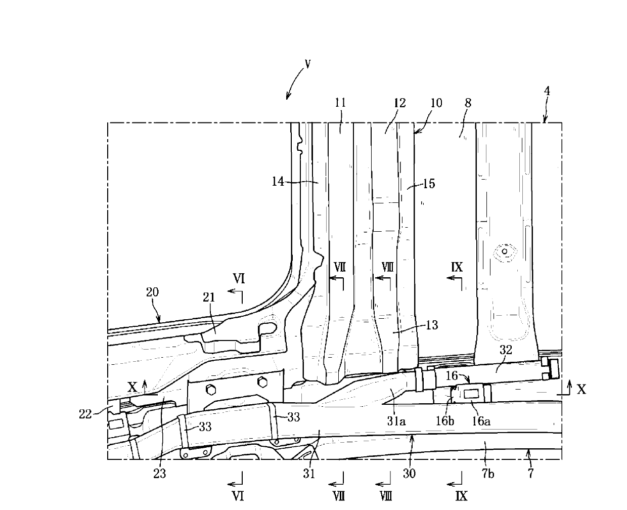
[0063] based on Figure 1 to Figure 10 Example 1 of the present invention will be described.

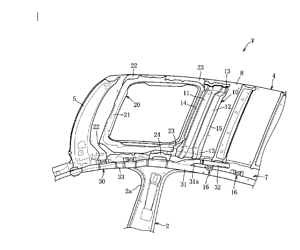
[0064] Such as figure 1 , figure 2 As shown, the vehicle V of this embodiment includes: a pair of left and right front pillars 1, a pair of left and right middle pillars 2, a pair of left and right rear pillars 3, and a roof 4 equipped with a sliding roof unit 20 on the front side. , and a pair of curtain airbag units 30 on the left and right.

[0065] Such as figure 1 As shown, at the upper ends of a pair of left and right front pillars 1, a front fascia 5 extending along the vehicle width direction is provided, and an upper portion of a windshield 6 is attached.

[0066] Such as figure 1 , figure 2 As shown, a pair of left and right center pillars 2 are provided approximately in the middle of the front seat (not shown) and the rear seat (not shown). Such as Image 6 As shown, the middle pillar 2 on the right side is set as follows: a closed cross-section extending in the ...

Embodiment 2

[0103] Next, based on Figure 11The upper body structure of the vehicle V according to the second embodiment will be described. In addition, only the structure different from the said Example 1 is demonstrated, and the same member as Example 1 is given the same code|symbol, and description is abbreviate|omitted.

[0104] The roof reinforcement 10A is provided so as to be offset rearward in the vehicle front-rear direction with respect to the pair of left and right center pillars 2 , and includes a substantially wedge-shaped wedge-shaped recess 17 extending across the entire width in the vehicle width direction. The wedge-shaped concave portion 17 is formed in such a way that the bottom is inclined toward the rear and upward, that is, the concave depth becomes shallower toward the rear side of the vehicle body. At the front end and the rear end of the wedge-shaped recessed portion 17, there are provided a front flange 14A and a rear flange 15A which are joined to the rear surf...


PUM


Abstract

An object of the present invention is to provide an upper vehicle-body structure of a vehicle which can ensure the stable inflation of the airbag for the both passengers seated in the front and rear seats, arranging the roof reinforcing member in back of the pillars with an offset distance. The upper vehicle-body structure comprises a pair of right-and-left center pillars (2), a pair of right-and-left roof side rails (7), and an inflator (7) provided on the inside, in a vehicle width direction, of the roof side rails and capable of supplying a gas pressure to an airbag (31), and a roof reinforcing member (10) which extends in the vehicle width direction over respective upper end portions of the center pillars or respective nearby portions to upper ends of the center pillars. The roof reinforcing member (10) includes a front concave portion (11) and a rear concave portion (12) which are concaved downward respectively. The inflator is arranged such that at least a portion of the inflator overlaps with the roof reinforcing member, and a depth of the rear concave portion overlapping with the inflator is shallower than that of the front concave portion positioned nearer the center pillars.

Description

technical field [0001] The present invention relates to an upper vehicle body structure of a vehicle provided with an inflator provided on the inside of a roof side rail in the vehicle width direction and capable of supplying air pressure to an airbag, and more particularly to a vehicle having a roof reinforcement member arranged offset from a pillar in the front-rear direction upper body structure. Background technique [0002] Conventionally, in a vehicle equipped with a curtain airbag, the curtain airbag is stored in a state of being folded along the inner surface in the vehicle width direction of the roof side rail, and the cabin side thereof is covered by the roof lining. As a result, when the vehicle collides with the side or rolls over, by supplying air pressure from the inflator to the curtain airbag, the curtain airbag inflates, opens the lower end of the roof lining, and protrudes toward the passenger compartment side along the side window glass. And unfold on the...

Claims


Application Information

Patent Timeline
Patent Type & Authority Applications(China)
IPC IPC(8): B62D25/00B62D25/06B60R21/213B60R21/26
CPCB60J7/02B62D25/04B62D25/06B62D25/00B60R21/213B60R21/26B60N3/026
Inventor 田中和弘藤井宏章清下大介
Owner MAZDA MOTOR CORP
Learn More