
Device and method for calibrating dynamic tracking precision of photoelectric tracking system

A photoelectric tracking system and dynamic tracking technology, applied in the field of optical metrology, can solve the problems of low precision, poor controllability of motion state, and many sources of uncertainty, and achieve the effect of accurate correction and high measurement accuracy

Inactive Publication Date: 2013-05-08
NO 27 RES INST CHINA ELECTRONICS TECH GRP
View PDF4 Cites 48 Cited by
  • Summary
  • Abstract
  • Description
  • Claims
  • Application Information

AI Technical Summary

Problems solved by technology

However, the above-mentioned traditional photoelectric tracking system dynamic characteristic test method has the disadvantages of strong subjectivity of measurement results, slow motion speed of simulated target, low precision, poor controllability of motion state, many sources of uncertainty, and high difficulty in system debugging. Meet the needs of military scientific research, military maintenance, military installation and troops

Method used


Image

  • Device and method for calibrating dynamic tracking precision of photoelectric tracking system
  • Device and method for calibrating dynamic tracking precision of photoelectric tracking system

Examples


Embodiment Construction

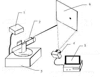
[0032] Such as figure 1 As shown, a dynamic tracking accuracy calibration device for a photoelectric tracking system includes a beacon light subsystem 1 for generating beacon light, a high-speed image acquisition system 4, and a processing subsystem. The beacon light subsystem 1 includes a A high-precision laser target simulator for simulating visible light targets, a laser target controller for transforming and controlling the movement of the laser beam, a first computer 3 for controlling the high-precision laser target simulator and the laser target controller, and The target plate 6 used to form the spot image required for the test, the high-speed image acquisition system 4 includes a high-speed camera for collecting the spot on the target plate 6, and the processing subsystem includes processing of the collected image data The second computer 5, the high-speed camera is connected to the second computer 5 through an image acquisition card.

[0033] The high-precision laser...


PUM


Abstract

The invention discloses a device and a method for calibrating the dynamic tracking precision of a photoelectric tracking system. The device comprises a beacon light subsystem used for generating beacon light, a high-speed image acquisition system and a processing subsystem, wherein the beacon light subsystem comprises a high-precision laser target simulator, a laser target controller, a first computer and a target plate; the high-speed image acquisition system comprises a high-speed camera; and the processing subsystem comprises a second computer. The beacon light subsystem consisting of a solid laser, a beam expander, a fast tilting mirror and a reflecting mirror is used for generating the beacon light to the target plate and can simulate targets with a plurality of motion modes and movement speeds through faculae, so that the precision of equipment can be tested persuasively. The faculae are acquired by the high-speed image acquisition system and the high test precision can be obtained by using a high-speed digital image processing technology, so that the photoelectric tracking system is quickly and accurately calibrated according to the measurement of the tracking precision.

Description

technical field [0001] The invention relates to the field of optical metrology, in particular to a dynamic tracking accuracy calibration device and method for a photoelectric tracking system in image processing. Background technique [0002] For the dynamic tracking accuracy index of the photoelectric tracking system, a lot of research has been done at home and abroad, and the gap between domestic and foreign countries is relatively large. Due to the military sensitive technology involved, there are not many detailed public reports. [0003] According to the existing public information, the United States has deployed hundreds of optical and photoelectric measurement equipment in the Baisha shooting range. Its data processing capability is strong and the measurement network is advanced, which can be used to detect any photoelectric tracking measurement equipment, but there are very few specific technical indicators. disclose. Our country has also done a lot of work on the ca...

Claims


Application Information

Patent Timeline
IPC IPC(8): G01C25/00
Inventor 李伟森王崇王学凯杜昌达曲凯张领军
Owner NO 27 RES INST CHINA ELECTRONICS TECH GRP
Learn More