Zipper puller and zipper with same
A technology for zippers and sliders, applied in the field of zippers, which can solve problems such as peeling, harshness, scratches on the pull piece or slider body, and achieve the effect of improving strength
- Summary
- Abstract
- Description
- Claims
- Application Information
AI Technical Summary
Problems solved by technology
Method used
Image
Examples
no. 1 approach
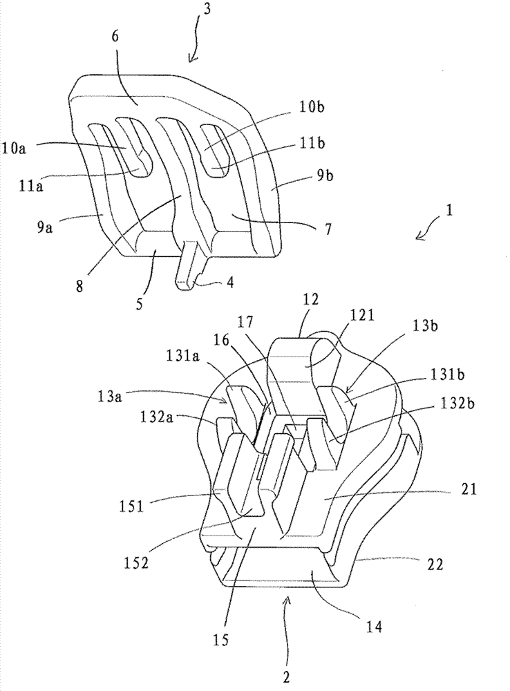
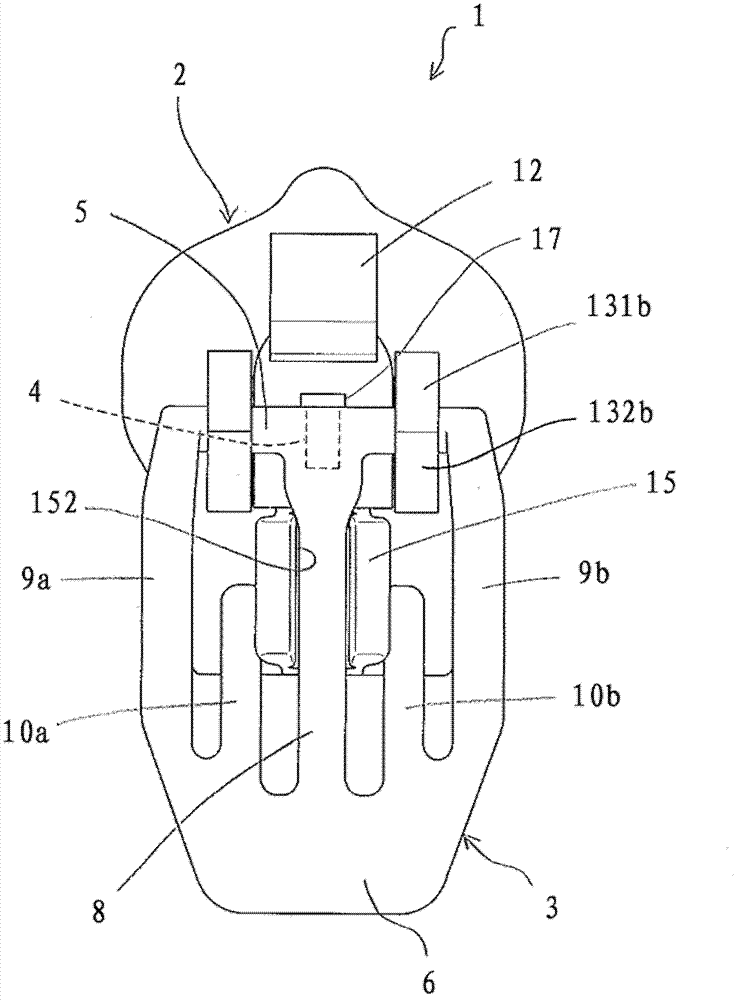
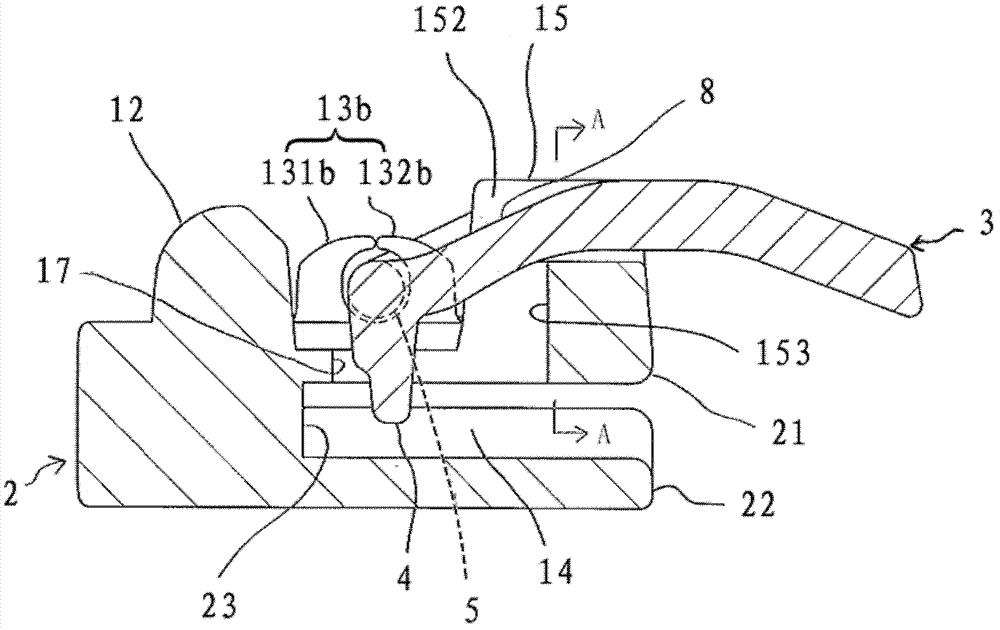
[0091] Figure 1 ~ Figure 5 This is a diagram showing the slider of the first embodiment of the present invention. figure 1 Is an exploded perspective view of the slider of the first embodiment of the present invention; figure 2 It is a top view of the slider of the first embodiment of the present invention, wherein the pull tab is in the first posture; image 3 Is a side cross-sectional view of the slider of the first embodiment of the present invention, wherein the pull tab is in the first posture; Figure 4 For along image 3 A cross-sectional view of line A-A in; Figure 5 This is a side cross-sectional view of the slider of the first embodiment of the present invention, wherein the pull tab is in the second posture.
[0092] Such as figure 1 As shown, the slider 1 has a slider body 2 and a pull tab 3, and the pull tab 3 can rotate between a first posture that is laid down on the slider body 2 and a second posture that is erected from the slider body 2. In this embodiment, the...
no. 2 approach
[0103] Figure 6 ~ Figure 7 This is a diagram showing the slider of the second embodiment of the present invention. Image 6 It is a top view of the slider of the second embodiment of the present invention, wherein the pull tab is in the first posture; Figure 7 This is a side cross-sectional view of the slider of the second embodiment of the present invention, in which the pull tab is in the second posture. In addition, in the description of the present embodiment, the same reference numerals are given to the same or equivalent parts as in the first embodiment, and the description of the parts is omitted.
[0104] Such as Image 6 as well as Figure 7 As shown, compared with the first embodiment, in the second embodiment, the rod and the first groove for accommodating the rod are not formed. And, instead of providing a first column part in the first embodiment, in the second embodiment, on the front side of the slider body 2, there are provided from the slider body 2 along the op...
no. 3 approach
[0108] Figure 8 ~ Figure 9 This is a diagram showing the slider of the third embodiment of the present invention. Figure 8 It is a top view of the slider of the third embodiment of the present invention, wherein the pull tab is in the first posture; Picture 9 This is a side cross-sectional view of the slider of the third embodiment of the present invention, in which the pull tab is in the second posture. In addition, in the description of the present embodiment, the same reference numerals are given to the same or equivalent parts as in the first embodiment, and the description of the parts is omitted.
[0109] Such as Figure 8 as well as Picture 9 As shown, compared with the first embodiment, in the third embodiment, no recesses are formed, but between a pair of left and right support portions 13a, 13b to penetrate the upper plate 21 of the slider body 2 in the vertical direction. According to the method, the hole 17 communicating with the element passage 14 is directly form...
PUM
 Abstract
Description
Claims
Application Information
 - Generate Ideas
- Intellectual Property
- Life Sciences
- Materials
- Tech Scout
- Unparalleled Data Quality
- Higher Quality Content
- 60% Fewer Hallucinations
Browse by: Latest US Patents, China's latest patents, Technical Efficacy Thesaurus, Application Domain, Technology Topic, Popular Technical Reports.
© 2025 PatSnap. All rights reserved.Legal|Privacy policy|Modern Slavery Act Transparency Statement|Sitemap|About US| Contact US: help@patsnap.com


