Adjustable diffuser structure and compressor using adjustable diffuser structure

A diffuser and compressor technology, applied in the field of compressors, can solve problems such as complex driving structure and inability to widely apply compressor structures

Active Publication Date: 2015-06-17
GREE ELECTRIC APPLIANCES INC
View PDF4 Cites 2 Cited by
  • Summary
  • Abstract
  • Description
  • Claims
  • Application Information

AI Technical Summary

Problems solved by technology

The structure of the adjustable diffuser in the prior art has multiple driving methods, but the driving structure is complicated and cannot be widely applied to various compressor structures

Method used


Image

  • Adjustable diffuser structure and compressor using adjustable diffuser structure
  • Adjustable diffuser structure and compressor using adjustable diffuser structure

Examples


Embodiment Construction

[0018] The embodiments of the present invention will be described in detail below with reference to the accompanying drawings, but the present invention can be implemented in many different ways defined and covered by the claims.

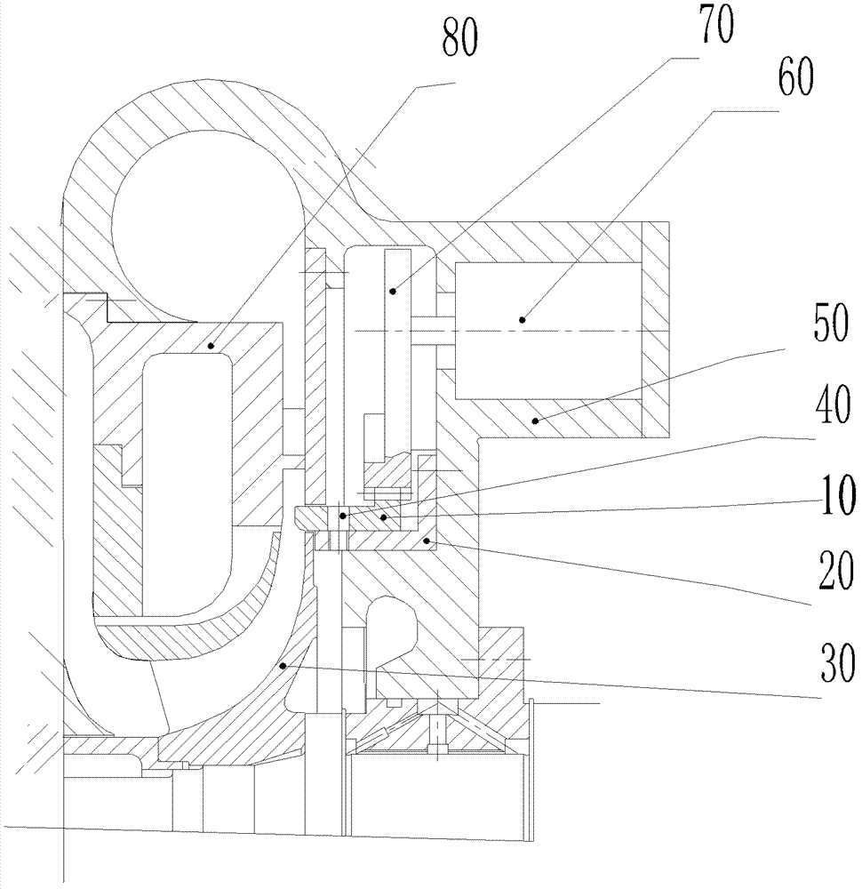
[0019] figure 1 A schematic side sectional view of a centrifugal compressor with an adjustable diffuser structure according to an embodiment of the present invention is shown in . Centrifugal compressor comprises impeller 30 and vane diffuser 80, an adjustable diffuser structure is set between the air outlet of impeller 30 and the inlet of vane diffuser 80, the adjustable diffuser of this adjustable diffuser structure The device 10 is installed on a sleeve 20, and the sleeve 20 is fixedly connected to the casing 50 of the centrifugal compressor.

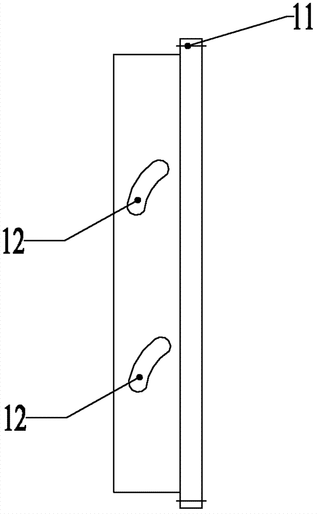
[0020] see figure 2 The specific structure of the adjustable diffuser 10 in the adjustable diffuser structure shown in . The adjustable diffuser 10 of the adjustable diffuser structure is cylindrical, ...


PUM


Abstract

The invention provides an adjustable diffuser structure, which comprises a sleeve, an adjustable diffuser and an electric motor, wherein the sleeve is fixedly connected with the inside of a tank body of a compressor, the adjustable diffuser is connected with the sleeve and is movably arranged between an air flow outlet of an impeller of the compressor and an inlet of a blade diffuser, and the electric motor is in driving connection with the adjustable diffuser. The adjustable diffuser structure has the main advantages that the structure of the whole driving system is concise and independent, so the adjustable diffuser structure is suitable for various types of compressor structures, such as centrifugal compressors and a two-stage impeller outlet of a two-stage blade compressor, and the compressors can always run at the highest power; and meanwhile, through the arrangement of an adjustable section, the reflux can be prevented, so the occurrence of surge can be effectively avoided.

Description

technical field [0001] The invention relates to the field of compressors, in particular to an adjustable diffuser structure for the compressor and a compressor with the adjustable diffuser structure. Background technique [0002] In centrifugal compressors, vane diffusers are generally provided in order to improve work efficiency. However, when the working conditions change, the velocity and direction of the airflow at the vane inlet of the vane diffuser will change, which will have an impact on the vane diffuser, the inlet loss will increase, the efficiency will drop sharply, and the flow rate will decrease at the same time, which will easily cause the vane diffuser Surge, making the stable working area smaller. In order to avoid surge and obtain a wide stable working range, an adjustable diffuser structure can be set at the outlet of the impeller. The structure of the adjustable diffuser in the prior art has multiple driving modes, but the driving structure is complicate...

Claims


Application Information

Patent Timeline
Patent Type & Authority Patents(China)
IPC IPC(8): F04D29/46
CPCF04D29/464F05D2250/52
Inventor 钟瑞兴张治平蒋彩云蒋楠谢蓉傅鹏闫秀兵
Owner GREE ELECTRIC APPLIANCES INC
Why Eureka
Try Eureka