
High-position inclined E-type ventilation system of coal face

A technology for coal mining face and ventilation system, which is applied in mine/tunnel ventilation, mining equipment, earth-moving drilling, etc. problems, to achieve the effect of reducing road maintenance problems, saving manpower and material resources, and improving economic benefits

Inactive Publication Date: 2013-05-01
JIANGSU VOCATIONAL INST OF ARCHITECTURAL TECH
View PDF4 Cites 15 Cited by
  • Summary
  • Abstract
  • Description
  • Claims
  • Application Information

AI Technical Summary

Problems solved by technology

[0002] With the continuous strengthening of the modern production technology of coal mines, the intensity of comprehensive mechanized coal mining is increasing, the production is concentrated, and the advancement speed is fast, so that the gas gushing out of the mining face has the characteristics of high intensity, large quantity and unbalanced gushing. Due to the large mining height, long mining area and large strike length, the goaf area is large, resulting in serious overrun of return air flow and local gas (especially in the upper corner), which poses a great threat to safe production
[0003] At present, the U-shaped ventilation system of the working face is commonly used because the gas concentration in the upper corner and the return air channel often exceeds the limit, which seriously affects the normal production of the coal mine, restricts the popularization and application of high-yield and efficient coal mining technology and the improvement of comprehensive economic benefits.
In order to ensure a higher output, a certain coal cutting speed must be ensured, so it is difficult to effectively control the coal wall and coal gas gushing out of the working face. Generally, the gas gushing out of coal can only be reduced by pre-pumping

Method used


Image

  • High-position inclined E-type ventilation system of coal face
  • High-position inclined E-type ventilation system of coal face
  • High-position inclined E-type ventilation system of coal face

Examples


Embodiment Construction

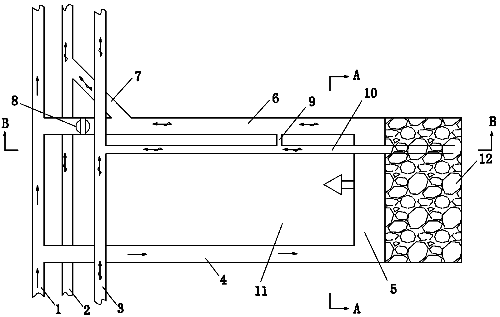
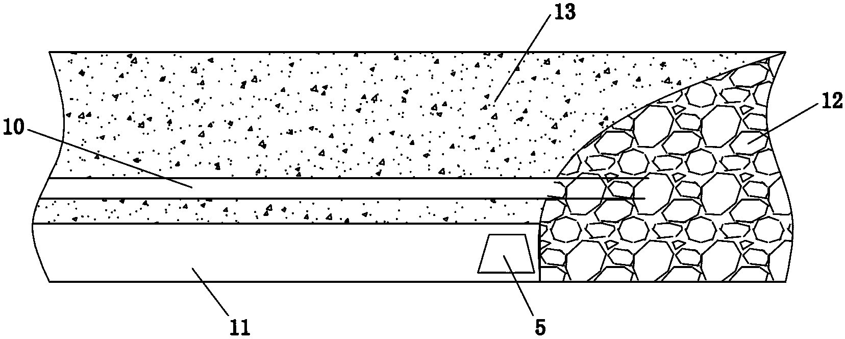
[0015] As shown in the figure: a high-level partial E-type ventilation system in a coal mining face, an air inlet lane 4 and a return air lane 6 are arranged in the coal mining area 11, and the return air lane and the air inlet lane are close to the return air lane. There is a high-level gas discharge lane 10 in the upper rock layer 12 of the coal seam of the wind lane, forming a high-level partial "E" ventilation system of "one inlet and two loops". pressure, restrain the gas in the goaf 12 from gushing to the upper corner of the mining face and the return airway, and guide the gas in the goaf to move to the special gas roadway 3.

[0016] One side of the air inlet alley and the air return alley is respectively equipped with an air inlet uphill 1, a return air uphill 2 and a special gas alley 3; between the return air uphill and the return air alley there is a return air level alley 7, and the return air There is also damper 8 on the wind alley.

[0017] A connecting lane 9 ...


PUM


Abstract

The invention relates to a ventilation system, of which the gas of an upper corner and a ventilation roadway is ultra-limit on a coal face, in particular to a high-position inclined E-type ventilation system of the coal face, and belongs to the technical field of coal mine safety equipment. A gas discharging high-position tunnel is formed between the ventilation roadway and an intake airway closed to a coal seam upper rock layer of the ventilation roadway, so as to form the high-position inclined E-type ventilation system with one intake airway and two ventilation roadways; the gas of a goaf can be restrained from pouring out to the upper corner and the ventilation roadway through adjusting the air quantity and air pressure of the ventilation roadway and the gas discharging high-position tunnel; and the gas of the goaf can be introduced to migrate to a gas special tunnel. The system uses a high-position tail tunnel, so that air leak congruence of the goaf is increased, and the gas accumulation of a U-type ventilation system is changed; and under the negative pressure of the ventilation system and / or the auxiliary extraction negative pressure functions, a high-position inclined E-type work face air power system is formed, so that the gas accumulation problem of the upper corner on the work face can be effectively solved.

Description

technical field [0001] The invention relates to a ventilation system for gas overrun in the upper corner of a coal mining working face and a return airway, in particular to a high-position partial E-type ventilation system for a coal mining working face, which belongs to the technical field of coal mine safety equipment. Background technique [0002] With the continuous strengthening of the modern production technology of coal mines, the intensity of comprehensive mechanized coal mining is increasing, the production is concentrated, and the advancement speed is fast, so that the gas gushing out of the mining face has the characteristics of high intensity, large quantity and unbalanced gushing. Due to the high mining height, long mining area and large strike length, the gob area is large, resulting in serious overrun of return air flow and local gas (especially in the upper corner), which poses a great threat to safe production. [0003] At present, the U-shaped ventilation s...

Claims


Application Information

Patent Timeline
IPC IPC(8): E21F1/00E21F7/00
Inventor 苗磊刚张国枢秦汝祥牛园园郑旋常万众
Owner JIANGSU VOCATIONAL INST OF ARCHITECTURAL TECH
Learn More