Rail-type vehicle
A rail-type and vehicle technology, applied in the field of rail-type vehicles, can solve the problems of poor riding comfort and sensitive response, and achieve the effect of preventing the poor riding comfort and reducing the guide wheel.
- Summary
- Abstract
- Description
- Claims
- Application Information
AI Technical Summary
Problems solved by technology
Method used
Image
Examples
no. 1 approach
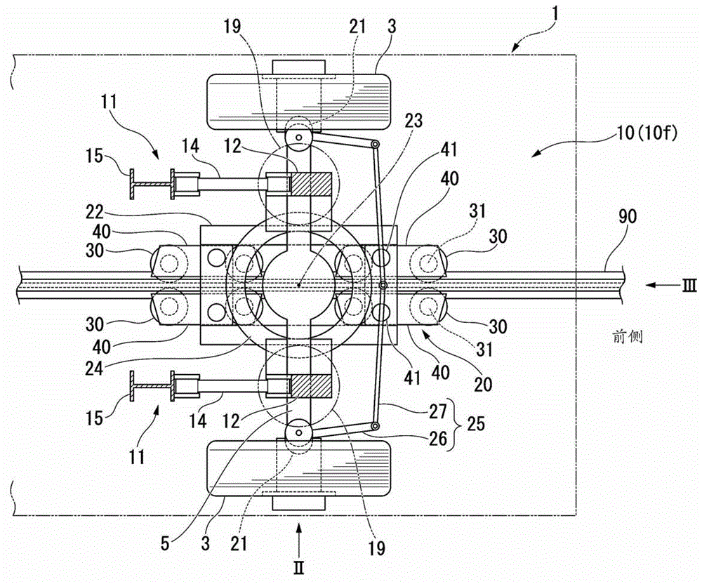
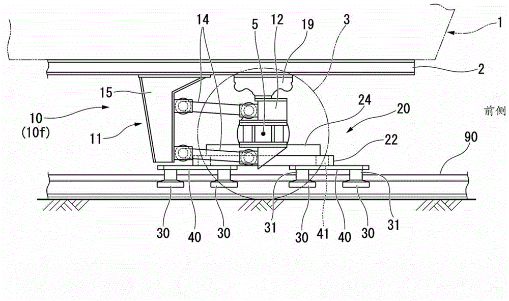
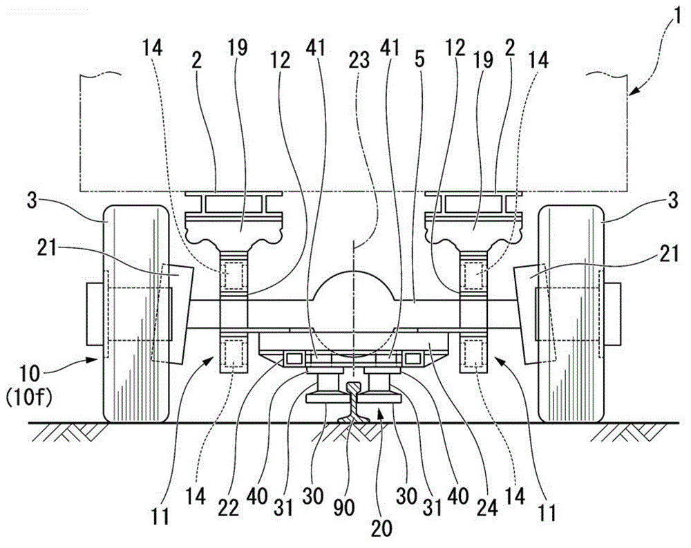
[0057] First, use Figure 1 to Figure 6 A first embodiment of the rail vehicle of the present invention will be described.
[0058] Such as Figure 5 As shown, the vehicle of this embodiment includes: a vehicle body 1 ; a front traveling device 10 f disposed on the lower front side of the vehicle body 1 ; and a rear traveling device 10 b disposed on the lower rear side of the vehicle body 1 .
[0059] Such as Figure 1 ~ Figure 3 As shown, each traveling device 10 (10f, 10b) has: a pair of left and right traveling wheels 3; an axle 5 connecting the pair of traveling wheels 3; a left and right pair of suspension devices 11 supporting the axle 5 and a pair of traveling wheels 3; The running wheels 3 face the steering guide 20 in the direction of the central guide rail 90 . In addition, the front side traveling device 10f and the rear side traveling device 10b have the same structure except that the front-back direction is reversed, and unless otherwise specified, the front sid...
no. 2 approach
[0092] First, use Figure 7 A second embodiment of the rail vehicle of the present invention will be described.
[0093] The vehicle steering guide device 20a of this embodiment is the same as the steering guide device 20 of the first embodiment, and also has a steering pin 21, a guide frame 22, a rotary bearing 24, a guide wheel 30, balance links 40, 44, and a steering link mechanism. 25.
[0094] In the present embodiment, the number of clamping pairs formed by two guide wheels 30 sandwiching the central guide rail 90 is that one traveling device has eight clamping pairs, and the clamping pairs are arranged along the front and rear sides of the guide frame 22. The directions are juxtaposed. Therefore, in the present embodiment, a total of sixteen (=8×2) guide wheels 30 are included in one traveling device 10 .
[0095] In the present embodiment, as the balance links 40 and 44, a balance link 40 (hereinafter referred to as W balance) in which two guide wheels 30 adjacent t...
no. 3 approach
[0102] Below, use Figure 8 and Figure 9 A third embodiment of the rail vehicle of the present invention will be described.
[0103] Such as Figure 8 As shown, like the steering guide device 20 of the first and second embodiments, the steering guide device 20b of the vehicle of this embodiment also has: a steering pin 21, a guide frame 22, a rotary bearing 24, a guide wheel 30, and a balance link 40,46 and steering linkage 25.
[0104] In the present embodiment, the number of clamping pairs formed by two guide wheels 30 sandwiching the central guide rail 90 is that one traveling device has five clamping pairs, and in the case of the front traveling device 10, On the front side of the rotating shaft 23, three clamping pairs are arranged in parallel in the front-rear direction, and on the rear side of the rotating shaft 23, two clamping pairs are arranged in parallel in the front-rear direction. Therefore, in this embodiment, one traveling device 10 has a total of ten (=5×...
PUM
 Abstract
Description
Claims
Application Information
 - Generate Ideas
- Intellectual Property
- Life Sciences
- Materials
- Tech Scout
- Unparalleled Data Quality
- Higher Quality Content
- 60% Fewer Hallucinations
Browse by: Latest US Patents, China's latest patents, Technical Efficacy Thesaurus, Application Domain, Technology Topic, Popular Technical Reports.
© 2025 PatSnap. All rights reserved.Legal|Privacy policy|Modern Slavery Act Transparency Statement|Sitemap|About US| Contact US: help@patsnap.com


