Waveguide ring coupler
A coupler and waveguide ring technology, which is applied in the field of broadband single-hole waveguide ring couplers, can solve the problems of narrow working bandwidth and achieve the effects of small insertion loss, convenient processing and assembly, and good standing wave at the port
- Summary
- Abstract
- Description
- Claims
- Application Information
AI Technical Summary
Problems solved by technology
Method used
Image

Examples
Embodiment 1
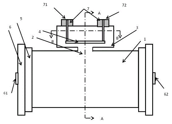
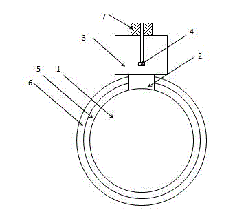
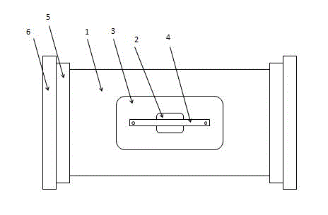
[0022] Such as figure 1 , figure 2 , image 3 As shown, a waveguide ring coupler includes a main waveguide 1, a coupling hole 2 is opened on the side wall of the main waveguide 1, a coupling cavity 3 is connected to the position of the coupling hole 2 of the main waveguide 1, and the coupling cavity 3 A coupling ring 4 is arranged inside, and the coupling ring 4 is connected with a coaxial port 7, and the coaxial port 7 is arranged outside the coupling cavity 3; and the two ends of the main waveguide 1 are also connected with transition steps 5, so A standard waveguide 6 is also provided at the end of the transition step 5 away from the main waveguide 1 .
[0023] The axis of the coupling ring 4 is parallel to the axis of the main waveguide 1 .
[0024] The angle formed by the axis of the coupling ring 4 and the axis of the main waveguide 1 is greater than 5 degrees.
[0025] The cross-sectional shape of the main waveguide 1 is circular.
[0026] The cross-sectional shap...
Embodiment 2
[0034] Such as figure 1 , figure 2 , Figure 4 As shown, the difference between this embodiment and the first embodiment is that the coupling hole 2 is circular in shape. The angle between the coupling hole 2, the coupling cavity 3 and the coupling ring 4 and the axis direction of the main waveguide 1 is greater than 5 degrees.
Embodiment 3
[0036] Such as figure 1 , figure 2 , Figure 5 As shown, the difference between the present embodiment and the first embodiment is that the coupling cavity 3 is circular in shape. The angle between the coupling hole 2, the coupling cavity 3 and the coupling ring 4 and the axis direction of the main waveguide 1 is greater than 5 degrees.
[0037] The main difference between the above three schemes is whether the shape of the coupling cavity 3 is rectangular or circular, whether the shape of the coupling hole 2 is rectangular or circular, whether there is an angle between the coupling hole 2, the coupling cavity 3 and the coupling ring 4 and the main waveguide 1 . In the specific implementation process, the size of the coupling hole 2, the size and shape of the coupling cavity 3, the size of the main waveguide 1 relative to the standard waveguide 6, and the angles of the coupling cavity 3, the coupling hole 2, and the coupling ring 4 relative to the main waveguide 1 can be ...
PUM
 Abstract
Description
Claims
Application Information
 - R&D
- Intellectual Property
- Life Sciences
- Materials
- Tech Scout
- Unparalleled Data Quality
- Higher Quality Content
- 60% Fewer Hallucinations
Browse by: Latest US Patents, China's latest patents, Technical Efficacy Thesaurus, Application Domain, Technology Topic, Popular Technical Reports.
© 2025 PatSnap. All rights reserved.Legal|Privacy policy|Modern Slavery Act Transparency Statement|Sitemap|About US| Contact US: help@patsnap.com