Transformer oil paper insulation state testing device and control method based on return voltage method
A technology of recovery voltage and state testing, applied in the direction of testing dielectric strength, etc., can solve the problems of large error, complicated operation, unsuitable for on-site use, etc., achieve high accuracy, broad application prospects, and easy operation
- Summary
- Abstract
- Description
- Claims
- Application Information
AI Technical Summary
Problems solved by technology
Method used
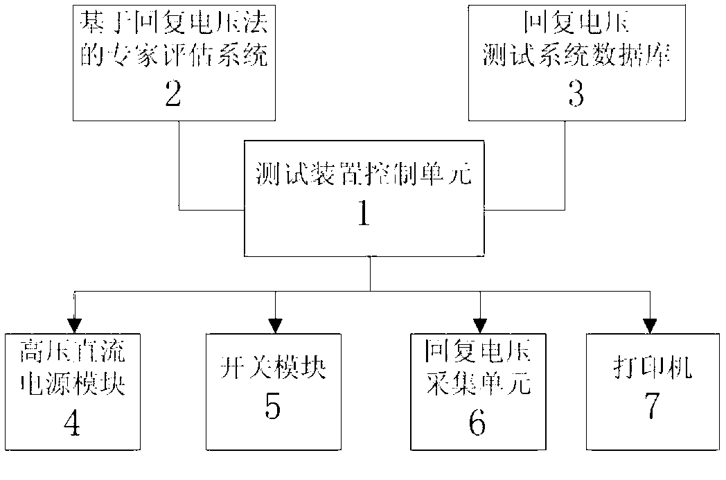
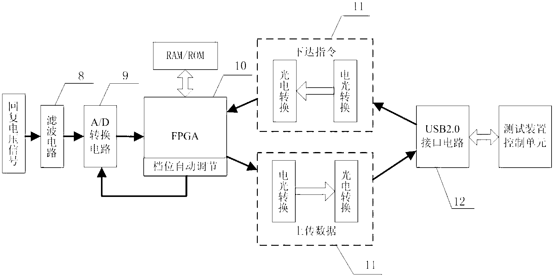
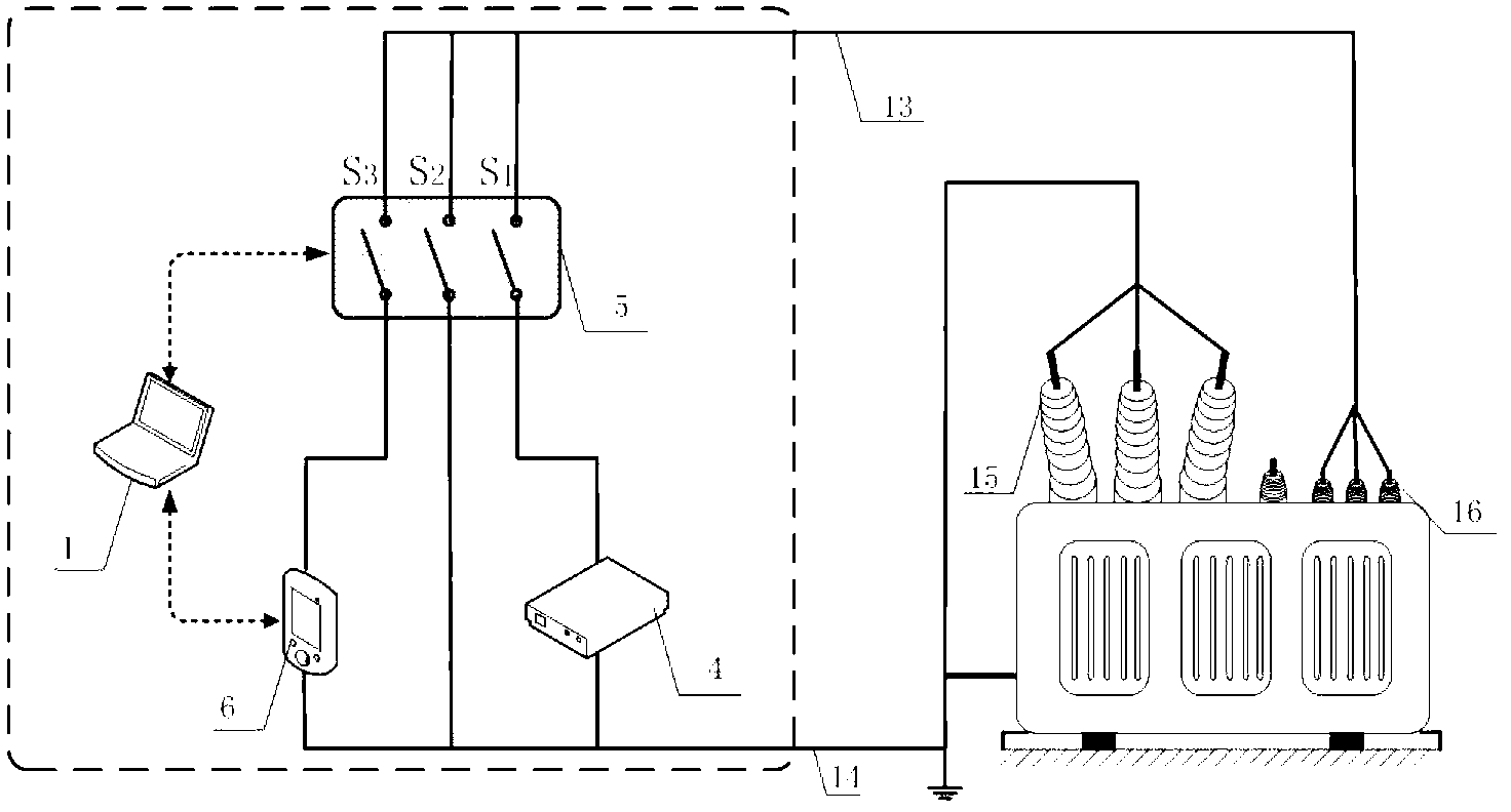
Image

Examples
Embodiment 1
[0035] A transformer factory used the present invention to test a transformer with a capacity of 150MVA that was put into operation in 1987 before (test product 1) and after transformation (test product 2). Set the test voltage U c =2000V, charging time T c =500s, the charging and discharging time is longer than T c / T d =2. The test results are shown in Table 1.
[0036] Table 1 Test results
[0037]
[0038] Note: U rmax — Maximum recovery voltage, unit: V
[0039] S i — The initial slope of the recovery voltage, unit: V / s
[0040] t cdom — central time constant, unit: s
Embodiment 2
[0042] A residential area implemented a power distribution equipment renovation project, shut down and dismantled 2 transformers, both with a capacity of 630kVA, put into operation in 1987 and 2001, and numbered 1# and 2# respectively. The two transformers are tested respectively by using the present invention. Set charging time U c =1000V, charging time T c =200s, the charging and discharging time is longer than T c / T d =2. The test results are shown in Table 2.
[0043] Table 2 Test results
[0044] Transformer number
u rmax (V)
S i (V / s)
t cdom (s)
Insulation state
1#
34.6
37.8
12.4
Insulation aging is serious
2#
9.3
12.5
38.1
Good insulation performance
[0045] From the test results in Table 1, it can be seen that the U rmax and S i Greater than sample 2, t cdom smaller than sample 2.
[0046] The test results show that: the insulation effect of sample 1 is very poor, and the...
PUM
 Abstract
Description
Claims
Application Information
 - R&D
- Intellectual Property
- Life Sciences
- Materials
- Tech Scout
- Unparalleled Data Quality
- Higher Quality Content
- 60% Fewer Hallucinations
Browse by: Latest US Patents, China's latest patents, Technical Efficacy Thesaurus, Application Domain, Technology Topic, Popular Technical Reports.
© 2025 PatSnap. All rights reserved.Legal|Privacy policy|Modern Slavery Act Transparency Statement|Sitemap|About US| Contact US: help@patsnap.com