Radar target detecting method

A radar target and detection method technology, applied in measurement devices, radio wave measurement systems, reflection/re-radiation of radio waves, etc., to achieve the effects of increasing average power, improving distance resolution, and improving signals

Inactive Publication Date: 2013-04-17
SICHUAN JIUZHOU ELECTRIC GROUP
View PDF4 Cites 17 Cited by
  • Summary
  • Abstract
  • Description
  • Claims
  • Application Information

AI Technical Summary

Problems solved by technology

[0007] It can be seen from the above table that the traditional radar detection technology us

Method used


Image

  • Radar target detecting method
  • Radar target detecting method
  • Radar target detecting method

Examples


Embodiment Construction

[0034] All features disclosed in this specification, or steps in all methods or processes disclosed, may be combined in any manner, except for mutually exclusive features and / or steps.

[0035] Any feature disclosed in this specification (including any appended claims, abstract and drawings), unless expressly stated otherwise, may be replaced by alternative features which are equivalent or serve a similar purpose. That is, unless expressly stated otherwise, each feature is one example only of a series of equivalent or similar features.

[0036] The radar target detection method among the present invention is characterized in that, comprises the following steps:

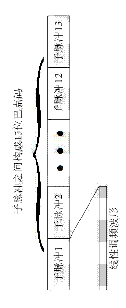
[0037] Step 1: Launch radar waves, including:

[0038] Step 11: Transmitting the first chirp sub-pulse;

[0039] Step 12: adjusting the phase of the first chirp sub-pulse to obtain a second chirp sub-pulse, so that the phase of the second chirp sub-pulse is equal to or opposite to that of the first chirp sub-pulse; ...


PUM


Abstract

The invention discloses a radar target detecting method, relates to a radar detection technology, and aims to provide a radar detecting method with both high range resolution and high velocity resolution for the condition that a conventional radar detecting technology which adopts a single waveform cannot simultaneously solve the problems of range ambiguity and velocity ambiguity. The radar target detecting method disclosed by the invention mainly comprises the following steps of: a step 1 of transmitting a radar wave signal, wherein the radar wave signal comprises m pulses, each pulse has a repetition period of T, each pulse is a radar wave pulse comprising k linear frequency modulation sub-pulses and a k-bit barker code or a combined barker code is formed by the k linear frequency modulation sub-pulses of each pulse; a step 2 of receiving an echo; a step 3 of judging whether a radar target is detected, executing a step 4 if yes, and repeating the steps 1 to 3 if the radar target is not detected; and the step 4 of determining a target distance and a moving velocity according to a radar echo signal.

Description

technical field [0001] The invention relates to radar detection technology, in particular to a radar target detection method with high distance resolution and high speed resolution. Background technique [0002] At present, the radar system obtains the distance information of the target by measuring the echo delay of the transmitted signal, and obtains the radial velocity of the target relative to the radar by measuring the Doppler frequency of the echo. [0003] The PRF used by conventional radars ranges from a few hundred Hz to hundreds of thousands of Hz. PRF (pulse repetition frequency) is the pulse repetition frequency, which represents the number of times the radar transmits pulse waves per second. For example, the pulse repetition period Tr of the radar is 1 millisecond, that is, the time interval from transmitting one pulse to the next pulse is 1 millisecond, then the pulse repetition frequency = 1 / Tr = 1000Hz. That's 1000 pulses per second. The choice of PRF has a...

Claims


Application Information

Patent Timeline
IPC IPC(8): G01S13/58G01S13/32
Inventor 赵怀坤张容权
Owner SICHUAN JIUZHOU ELECTRIC GROUP
Why Eureka
Try Eureka