
Multi-shaft crushing dryer of rotary drum

A technology of dryers and drums, applied in dryers, drying, non-progressive dryers, etc., can solve problems such as difficult installation and maintenance, long shaft length, easy deformation, etc., to prolong service life and reduce maintenance The effect of the probability of

Active Publication Date: 2013-04-17
JIAOZUO ZHENJIENNEG DRYING EQUIP DEV
View PDF9 Cites 4 Cited by
  • Summary
  • Abstract
  • Description
  • Claims
  • Application Information

AI Technical Summary

Problems solved by technology

For ordinary crushing shaft dryers, the installation direction of the crushing shaft is parallel to the axis direction of the drum. The length of the shaft is too long, and it is easy to deform when the temperature is high; installation and maintenance are also difficult.

Method used


Image

  • Multi-shaft crushing dryer of rotary drum
  • Multi-shaft crushing dryer of rotary drum
  • Multi-shaft crushing dryer of rotary drum

Examples


Embodiment 1

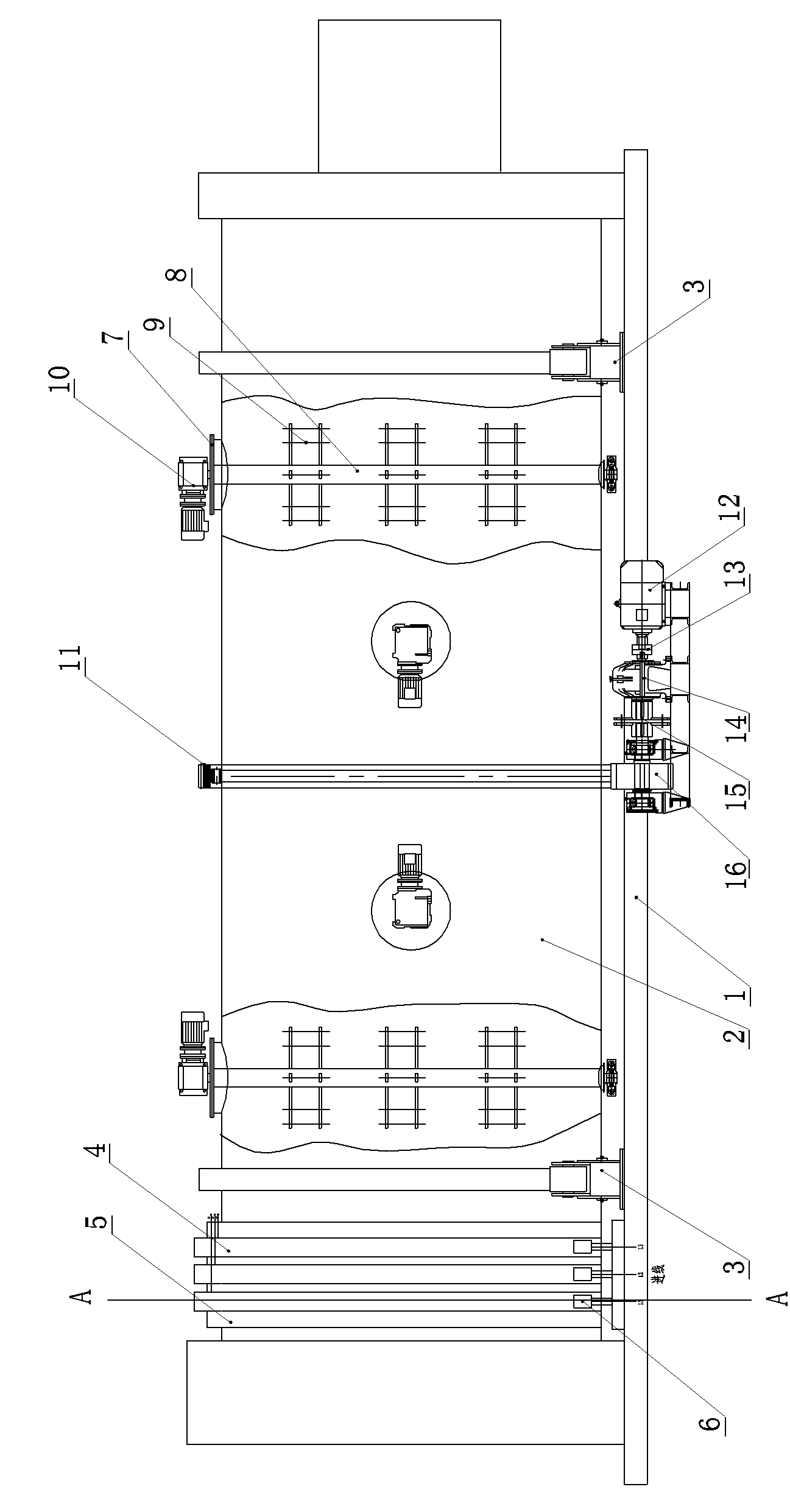
[0023] Embodiment one: see Figure 1-Figure 2 , a drum multi-shaft crushing dryer in the figure, including a dryer frame, a drum, a driving device, and a set of idlers. The set of idlers is installed on the frame of the dryer, and the drum is supported on On the roller set, the driving device drives the drum to rotate. The drum is equipped with several vertical crushing shafts crossing the wall of the drum, and the two ends of the vertical crushing shaft are installed on the wall of the drum through flanges. A number of vertical shafts are arranged in a cross; one end of each vertical shaft is connected with a crushing motor; the end of the drum is provided with at least two rotating rings, and the rotating rings are connected to the outer wall of the drum. Insulation between them, the transfer ring is connected to the crushing motor through wires, and a brush that matches and contacts the transfer ring is provided on the dryer frame at the lower part of the transfer ring, and...

Embodiment 2

[0028] Embodiment two: see Figure 3-Figure 4 , a drum multi-shaft crushing dryer in the figure, including a dryer frame, a drum, a driving device, and a set of idlers. The set of idlers is installed on the frame of the dryer, and the drum is supported on On the roller set, the driving device drives the drum to rotate. The drum is equipped with several vertical crushing shafts crossing the wall of the drum, and the two ends of the vertical crushing shaft are installed on the wall of the drum through flanges. Several vertical shafts are intersected; one end of each vertical shaft is connected to a crushing motor; the end of the dryer rack is provided with at least two wire transfer rings, and the wire transfer rings are connected to the The large frames of the dryer are insulated, the wire transfer ring is connected to the power supply through wires, and the outer wall of the drum is provided with a brush that matches and contacts the wire transfer ring, and the brush is connec...


PUM


Abstract

A multi-shaft crushing dryer of a rotary drum comprises a dryer big frame, the rotary drum, a driving device and a carrier roller group. The carrier roller group is arranged on the dryer big frame, the rotary drum is supported on the carrier roller group, the driving device drives the rotary drum to rotate, a plurality of vertical crushing shafts transversely penetrating through the drum wall are arranged on the rotary drum, two ends of the vertical crushing shafts are arranged on the drum wall of the rotary drum through flanges, and a plurality of vertical shafts are arranged in crossed mode. One end of each vertical shaft is connected with a crushing motor. At least two rotating linear rings are arranged at the end of the rotary drum, and electric brushes matched with the rotating linear rings are connected with a power supply device. A scattering shaft of the multi-shaft crushing dryer of the rotary drum is arranged in the diameter direction of the rotary drum and transversely penetrates through the rotary drum, the length of the scattering shaft is reduced so that the scattering shaft cannot deform due to over-temperature in the rotary drum, service life of the multi-shaft crushing dryer can be prolonged, and overhaul probability is reduced.

Description

technical field [0001] The invention relates to the technical field of drying equipment, in particular to a drum multi-shaft crushing dryer. Background technique [0002] In the drying industry, if you want to quickly dry the required materials, one must have is to fully disperse the materials in the drum, so that the hot air can fully contact the materials in a large area to achieve the drying effect. For ordinary crushing shaft dryers, the installation direction of the crushing shaft is parallel to the axis direction of the drum. The shaft length is too long, and it is easy to deform when the temperature is high; installation and maintenance are also difficult. Contents of the invention [0003] In order to solve the above problems, the present invention proposes a drum multi-shaft crushing and drying machine. [0004] The technical solution of the present invention is: a rotary drum multi-shaft crushing dryer, including a dryer frame, a rotary drum, a driving device, a...

Claims


Application Information

Patent Timeline
IPC IPC(8): F26B11/06F26B25/02F26B25/04
Inventor 岳正喜岳斌斌朱平安
Owner JIAOZUO ZHENJIENNEG DRYING EQUIP DEV
Learn More