
Wave form brightness adjustment and correction method of digital three-dimensional oscilloscope

A brightness adjustment and correction method technology, applied in the direction of digital variable display, etc., can solve the problems that it is difficult for users to observe abnormal signal waveforms, cannot reflect the value of high waveform capture rate of 3D digital oscilloscope, and lose waveforms, etc.

Inactive Publication Date: 2013-04-10
UNIV OF ELECTRONIC SCI & TECH OF CHINA
View PDF7 Cites 5 Cited by
  • Summary
  • Abstract
  • Description
  • Claims
  • Application Information

AI Technical Summary

Problems solved by technology

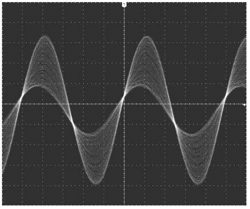
[0017] However, when using a digital 3D oscilloscope to observe the abnormal signals that may appear in the continuously recurring periodic signal, since the digital 3D oscilloscope has a high waveform capture rate, multiple waveforms captured in one refresh cycle are displayed on the LCD at the same time. However, because the probability of occurrence of abnormal signals is much lower than that of periodic signals, it is difficult for users to observe abnormal signal waveforms with very dark colors under the above-mentioned mapping relationship of linear uniform transformation, thus losing some details of the waveform and unable to reflect the three-dimensional The Value of High Waveform Capture Rate in Digital Oscilloscopes
In addition, if the user is only interested in the waveform with a certain hit probability when observing the mixed signal, since the probability of signal occurrence in the prior art has a linear and uniform relationship with the display brightness, the waveform of interest cannot be selected from the mixed signal. isolated for observation

Method used


Image

  • Wave form brightness adjustment and correction method of digital three-dimensional oscilloscope
  • Wave form brightness adjustment and correction method of digital three-dimensional oscilloscope
  • Wave form brightness adjustment and correction method of digital three-dimensional oscilloscope

Examples


Embodiment Construction

[0048] Specific embodiments of the present invention will be described below in conjunction with the accompanying drawings, so that those skilled in the art can better understand the present invention. It should be noted that in the following description, when detailed descriptions of known functions and designs may dilute the main content of the present invention, these descriptions will be omitted here.

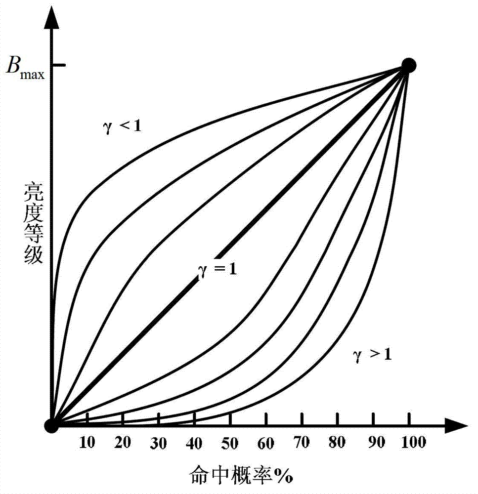
[0049] The digital three-dimensional oscilloscope developed according to the invention has three observation modes: positive power-law transformation mode, negative power-law transformation mode, and segmental transformation mode. Taking the digital three-dimensional oscilloscope as an example, the waveform brightness adjustment and correction method of the digital three-dimensional oscilloscope of the present invention will be described.

[0050] Step 1: The acquisition system uses an ADC with a precision of d bits to acquire the signal, and the number of sampling points f...


PUM


Abstract

The invention discloses a wave form brightness adjustment and correction method of a digital three-dimensional oscilloscope. According to hit probability of a signal sampling point, a user enables to-be-observed wave forms in a hit probability range to be displayed in a highlight mode through wave form brightness adjustment. In forward power law transformation, a wave form brightness grade increases with increase of the hit probability of the sampling point; and in reverse power law transformation, the wave form brightness grade reduces with increase of the hit probability of the sampling point. In the forward power law transformation and the reverse power law transformation, wave form brightness correction parameters can be adjusted to adjust wave form brightness distinguishability, and signals in different hit frequency ranges are conveniently observed. By the method of sectional transformation, the wave form sampling point falling in a certain range of the hit frequency can be specially focused on. According to the wave form brightness adjustment and correction method, wave forms in a specific frequency range can be observed and wave form display brightness can be changed at will, the defect of an existing digital three-dimensional oscilloscope is overcome, and the obtained wave forms can display more detail information.

Description

technical field [0001] The invention belongs to the technical field of digital three-dimensional oscilloscopes, and more specifically relates to a method for adjusting and correcting waveform brightness of a three-dimensional oscilloscope. Background technique [0002] A digital three-dimensional oscilloscope (DTO for short) refers to a digital storage oscilloscope that can not only capture and display the time-amplitude (event) information of a signal, but also display the probability of occurrence of different events with different brightness or color levels ( Digital Storage Oscilloscope, referred to as DSO). Digital 3D oscilloscopes usually have a high waveform capture rate. The waveform capture rate of an oscilloscope refers to the number of waveforms that the oscilloscope can capture and display per unit time, usually expressed in waveform amplitudes / second (wfms / s) (taken from "GB / T 15289-2009 Digital Storage Oscilloscope Specifications" Definition) [0003] The wa...

Claims


Application Information

Patent Timeline
IPC IPC(8): G01R13/02
Inventor 张沁川杨扩军邱渡裕蒋俊李为
Owner UNIV OF ELECTRONIC SCI & TECH OF CHINA
Learn More