Molding device and molding method
A one-sided, polygonal technology, applied to other household appliances, optical components, household appliances, etc., can solve problems such as inability to fit, tapered guides cannot be fitted, etc., to improve positioning accuracy, increase rigidity, and reduce wear. Effect
- Summary
- Abstract
- Description
- Claims
- Application Information
AI Technical Summary
Problems solved by technology
Method used
Image

Examples
no. 1 approach
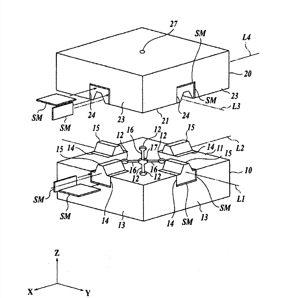
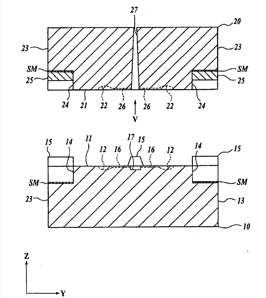
[0089] figure 1 It is a partial perspective view of the molding apparatus which implements the 1st Embodiment of the molding method of this invention. figure 2 It is an axial cross-sectional view of a part of the molding apparatus according to the first embodiment. exist figure 1 , 2 In the above, the mold clamping direction is the vertical direction, that is, the Z direction, and the mold clamping orthogonal directions are defined as the X direction and the Y direction. exist figure 1 Among them, the fixed-side mold 10 as the first mold is in the shape of a rectangular frame, is fixed on a frame not shown in the figure, forms four transfer surfaces 12 on the upper surface 11, and forms a cutout portion 14, and the cutout portion 14 is formed on the upper surface 11. The upper surface 11 and the sides 13 are exposed. Each notch part 14 is a rectangular parallelepiped recessed part of the same shape, and accommodates the protrusion 15 inside. The coefficient of thermal e...
no. 2 approach
[0118] Figure 10 is the second embodiment with figure 1 The same stereogram. In this embodiment, the fixed-side mold 10' integrally forms the tapered portion 15c as the convex portion, and the movable-side mold 20' integrally molds the groove portion 25c as the concave portion. In addition, in the present embodiment, the transfer surface 22 is formed on the end surface of the insert C1, and the insert C1 is inserted into the opening 10a' of the fixed-side mold 10'. Moreover, the transfer surface (not shown) which opposes the transfer surface 22 is formed in the end surface of the insert C2, and the insert C2 is inserted into the opening 20a' of the movable side mold 20'.
[0119] In addition, besides inserting the mold inserts C1 and C2 directly into the openings of the molds 10' and 20', they can also be inserted through, for example, the figure 1 , figure 2 , Figure 5 and Figure 6 Parts described as reference numerals 34, 35 among others insert the mold insert into...
no. 3 approach
[0125] Figure 15 It is a partial cross-sectional view of a molding apparatus according to a third embodiment of the molding method of the present invention. Figure 16 It is cut with the arrow II-II line Figure 15 The structure of , and the partial cross-sectional view viewed along the direction of the arrow. Figure 17 It is cut with the arrow III-III line Figure 15 The front view of the structure and looking in the direction of the arrow. Figure 18 It is a perspective view showing a template and a block. Here, a horizontal forming device is shown, but a vertical forming device may also be used. Here, let the mold clamping direction be the Z direction, and let the mold clamping orthogonal directions be the X direction and the Y direction.
[0126] exist Figure 15 11A of fixed-side mounting plates are fixed to an unshown frame. On the left side in the drawing of the fixed-side mounting plate 11A, a rectangular-plate-shaped fixed-side profile 12A is fixed with unill...
PUM
| Property | Measurement | Unit |
|---|---|---|
| wavelength | aaaaa | aaaaa |
| wavelength | aaaaa | aaaaa |
| diameter | aaaaa | aaaaa |
Abstract
Description
Claims
Application Information
 - Generate Ideas
- Intellectual Property
- Life Sciences
- Materials
- Tech Scout
- Unparalleled Data Quality
- Higher Quality Content
- 60% Fewer Hallucinations
Browse by: Latest US Patents, China's latest patents, Technical Efficacy Thesaurus, Application Domain, Technology Topic, Popular Technical Reports.
© 2025 PatSnap. All rights reserved.Legal|Privacy policy|Modern Slavery Act Transparency Statement|Sitemap|About US| Contact US: help@patsnap.com